Custom BMS Design and Engineering
The 5-Dimensional Multi-Cell BMS Architecture Protocol
Modern Battery Management System (BMS) design is a mission-critical sub-discipline of electrical engineering that coordinates mixed-signal hardware, real-time embedded firmware, and electrochemistry state estimation. Off-the-shelf protection circuit modules (PCMs) fail in high-reliability applications because they treat lithium packs as simple voltage-clamped loads, neglecting dynamic impedance shifts, thermal gradient propagation, and non-linear cell decay.
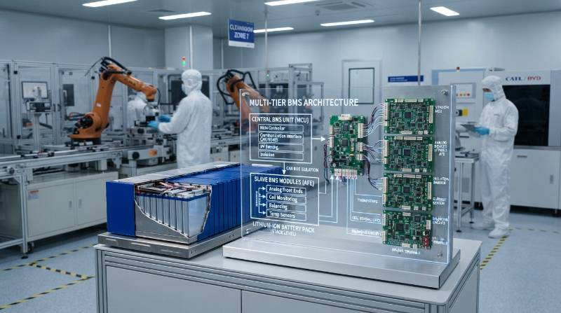
Engineering robust custom BMS design and engineering solutions requires a systematic methodology. Sichuan Changhong Group’s battery engineering division relies on the 5-Dimensional Multi-Cell BMS Architecture Protocol to govern every phase of hardware and firmware realization:
- Dimension 1: Sensing Precision & Microsecond Protection: Synchronous cell voltage sampling (<±1.5mV) paired with pure analog hardware comparator response (<100µs) for overcurrent and short-circuit faults.
- Dimension 2: Non-Linear State Estimation Accuracy: Model-based Extended Kalman Filtering (EKF) ensuring state of charge (SOC) error limits below ±1.5% across flat LiFePO4 open-circuit voltage (OCV) profiles.
- Dimension 3: Dynamic Thermal & Low-Temperature Management: Active boundary controls from -45°C to +80°C, including self-heating algorithms that eliminate dendrite formation during sub-zero fast charging.
- Dimension 4: Balancing Efficiency & Topology Scalability: Dynamic active inductive charge-redistribution (>1.5A) or thermally bounded passive bleed networks adapted to pack size and cycle demands.
- Dimension 5: Multi-Tier Functional Safety Redundancy: Hardware and software segregation meeting ISO 26262 ASIL-D, IEC 61508 SIL-3, and ISO 13485 medical life-support reliability standards.
| Architecture Metric | Generic Commodity PCM | Industrial Smart BMS (Changhong JHY) |
|---|---|---|
| Voltage Measurement Accuracy | ±25mV to ±50mV | ±1.0mV to ±1.5mV (16-bit Σ-Δ ADC) |
| Short-Circuit Response Time | 250µs – 1200µs (Firmware delay) | <100µs (Pure hardware comparator) |
| SOC Tracking Error (LFP) | ±8% to ±15% (Coulomb drift) | <±1.5% (Adaptive Dual-EKF) |
| Balancing Topology | Passive (30-50mA static bleed) | Active Inductive (1A–5A) or Dynamic Passive |
| Failure Rate Target | >1000 PPM (Unverified SMT) | ≤300 PPM (0.03%) with 100% ATE & HIL |
Core Hardware Architecture: AFE Selection, Gate Drivers, and Protection
The hardware foundation of an industrial BMS dictates pack safety, signal-to-noise ratio (SNR), and survivability during extreme load faults. High-reliability systems utilize dedicated Analog Front End (AFE) ICs—such as the Texas Instruments BQ76952/BQ79616 series or Analog Devices LTC6811/LTC6813 controllers—interfaced with industrial-grade microcontrollers via isolated SPI or redundant I2C buses.
AFE selection must align precisely with cell topology and string count. In configurations ranging from 3S up to 192S+ high-voltage stacks, synchronous internal sample-and-hold circuits eliminate phase shifts across series voltage readings during dynamic current pulses.
Current sensing utilizes low-temperature-coefficient (TCR < 50ppm/°C) Manganin or electron-beam welded shunt resistors placed in the high-current path. For high-voltage packs exceeding 400V, fluxgate or Hall-effect closed-loop current transducers provide essential galvanic isolation between power and logic rails.
Power path switching requires robust bidirectional N-channel power MOSFET arrays. High-side switching architectures eliminate common-mode ground reference shifting during switch events, simplifying diagnostic communication. MOSFET gate driver networks require charge-pump regulation with active pull-down circuitry capable of delivering 2A to 5A peak gate discharge current.
Engineering Rule of Thumb: Hardware short-circuit protection (SCP) must NEVER depend on MCU firmware execution. A discrete analog comparator circuit monitoring shunt voltage drop must directly assert the gate driver pull-down stage, shutting off the discharge path in under 100 microseconds to prevent MOSFET avalanche breakdown.
Galvanic Isolation and High-Current Thermal Dissipation Layout
Managing continuous currents from 100A to 300A on high-density PCBAs introduces severe thermal and electromagnetic compatibility (EMC) constraints. Copper traces must be engineered using 3oz to 6oz copper pours, supported by solid thermal via arrays (0.3mm diameter with 0.8mm pitch) tied directly to underlying aluminum cooling plates or heatsinks.
High-voltage battery stacks mandate galvanic barrier separation (>2500Vrms isolation) between low-voltage microcontrollers and the high-voltage pack potential. Capacitive and magnetic digital isolators (such as Analog Devices isoSPI or TI ISO77xx) isolate serial telemetry buses, preserving signal integrity according to ISO 26262 automotive safety standards.
Embedded Firmware Algorithms: SOC, SOH, and State Estimation
Accurate state estimation represents the core intellectual property of smart BMS engineering. Traditional Coulomb counting suffers from open-loop numerical integration drift, while pure OCV lookup tables fail completely on flat-discharge electrochemistries like lithium iron phosphate.
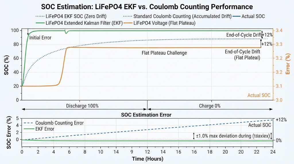
For custom LiFePO4 battery systems, where the open-circuit voltage varies by only 10mV across a 20% to 80% SOC window, our firmware implements an Adaptive Extended Kalman Filter (EKF) coupled with an Equivalent Circuit Model (ECM).
The EKF recursively processes real-time terminal voltage, current load, and surface temperature inputs. It continuously recalculates the cell’s internal state variables ($x_k = [\text{SOC}_k, V_{1,k}, V_{2,k}]^T$) and covariance matrices, achieving SOC tracking error below ±1.5% across dynamic charging and discharging duty cycles.
State of Health (SOH) algorithms calculate pack degradation by cross-referencing high-precision charge integration during full cycles with dynamic Equivalent Series Resistance (ESR) shifts calculated during transient current steps ($\Delta R = \Delta V / \Delta I$). Firmware updates are deployed via dual-bank bootloaders supporting cryptographic authentication over CAN FD or BLE.
Cell Balancing Architecture: Active Inductive vs. Passive Dissipative Shunt
Manufacturing tolerances inevitably cause minor cell capacity and impedance variations. Uncorrected cell mismatch leads to premature voltage cutoff on the weakest cell, curtailing usable pack capacity.
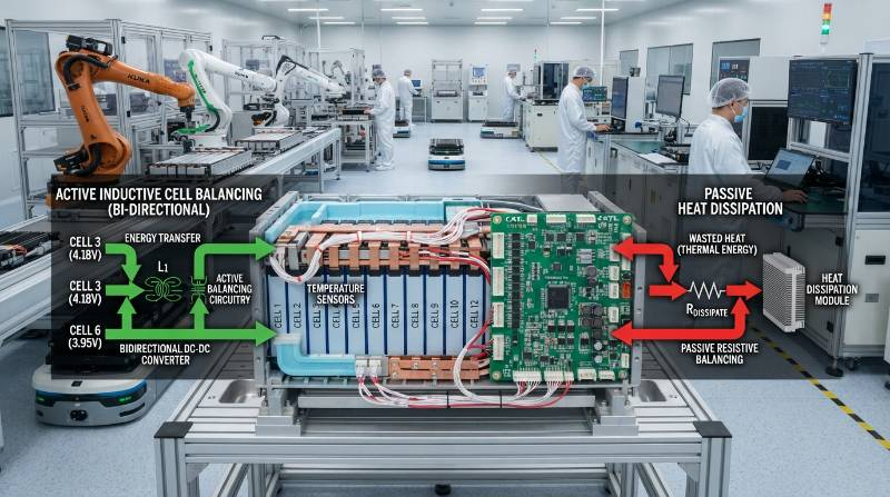
The choice between passive dissipative balancing and active charge-shuttling balancing involves clear engineering trade-offs regarding efficiency, cost, and thermal overhead:
- Passive Dissipative Balancing: Uses low-side MOSFETs and precision power resistors to bleed excess energy as heat from the highest-voltage cells during the top-of-charge cycle (50mA to 200mA balance current). This approach is cost-effective and compact for pack capacities under 20Ah, but is limited by thermal dissipation bottlenecks on dense PCBAs.
- Active Inductive/Capacitive Balancing: Employs bidirectional DC-DC flyback converters or switched-capacitor topologies to route energy dynamically from high-voltage cells to lower-voltage cells at rates of 1.0A to 5.0A. While adding circuit complexity, active balancing is essential for large packs (>100Ah) in utility and industrial storage systems, reclaiming 5% to 10% of pack capacity otherwise lost to cell mismatch without creating localized thermal hotspots.
Extreme Scenario Engineering: Arctic Sub-Zero Heating and ISO 13485 Medical Redundancy
China Battery Manufacturer specializes in high-reliability battery solutions for mission-critical operating environments that exceed standard commercial specifications.
In sub-zero climates, charging lithium cells below 0°C leads to irreversible lithium plating on the graphite anode, causing severe capacity fade and internal short-circuits. Our extreme low-temperature batteries incorporate dynamic thermal management firmware that orchestrates integrated silicone heater jackets or internal PTC heating elements. The BMS routes incoming charge power to warming elements until the core pack temperature reaches +5°C, only then enabling main battery charge pathways across an operating envelope down to -45°C.
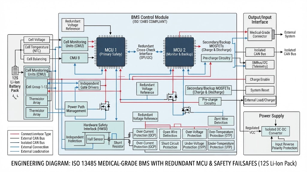
For life-support equipment such as portable mechanical ventilators, infusion pumps, and defibrillators, we engineer medical-grade systems under strict ISO 13485 medical device batteries manufacturing controls. These mission-critical BMS architectures incorporate:
- Dual-Redundant Primary & Secondary Protections: Independent secondary overvoltage detection ICs wired to chemical thermal fuses that irreversibly blow if primary MOSFET switches fail to open.
- Zero-Volt Deep Sleep Recovery: Low-quiescent-current sleep circuits (<5µA) coupled with controlled pre-charge trickle current drivers that safely recover over-discharged cells without triggering latch-up faults.
- 300 PPM Defect Guarantee: Full component traceability, automated optical inspection (AOI), and in-circuit automated testing ensuring extreme production consistency.
Industrial Telemetry & Communication Protocols
Modern battery packs operate as intelligent nodes in broader industrial networks. BMS communication hardware must maintain high common-mode noise rejection and galvanic isolation to operate reliably alongside variable-frequency drives, high-power inverters, and industrial chargers.
For utility and commercial infrastructure, our commercial & industrial energy storage systems (BESS) leverage daisy-chained RS485 Modbus RTU telemetry alongside dual-ring CAN 2.0B / CAN FD networks. This dual-bus architecture isolates internal rack-level cell telemetry from supervisory master controller traffic, enabling sub-millisecond fault isolation across multi-megawatt installations.
| Protocol | Bandwidth / Max Distance | Primary Application Target | Key Engineering Advantage |
|---|---|---|---|
| CAN 2.0B / CAN FD | Up to 5 Mbps / 40m | EVs, Heavy AGVs, Solar ESS | Deterministic arbitration, high noise immunity |
| RS485 (Modbus RTU) | 115.2 kbps / 1200m | Multi-rack BESS, Telecom UPS | Multi-drop capability over long physical distances |
| SMBus / I2C | 100-400 kbps / <1m | Medical Devices, Robotics, Drones | Standardized smart battery commands, ultra-low power |
| BLE / Cellular IoT | Wireless / Cloud Gateway | Asset Tracking, Rental Micro-mobility | Direct mobile app pairing & cloud fleet telemetry |
Functional Safety Standards, Automated ATE/HIL Testing, and DFM
Battery management systems for industrial, medical, and motive platforms must comply with strict international functional safety standards, including IEC 62133-2, UL 2054, UL 1973, and ISO 26262 (ASIL-C/D). Meeting these standards requires end-to-end design verification and robust Design for Manufacturability (DFM) discipline.
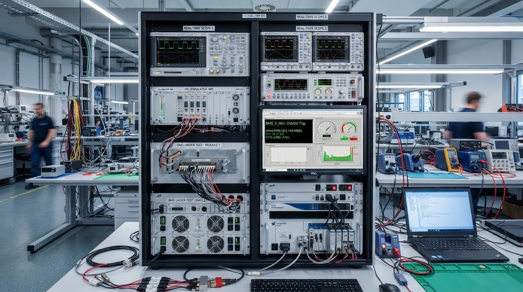
At Sichuan Changhong Group / JHY Battery, BMS production quality is maintained through automated hardware validation and testing workflows:
- Hardware-in-the-Loop (HIL) Simulation: Every custom firmware build undergoes automated HIL regression testing. Digital test rigs simulate individual cell voltages, contactor bounce, isolated ground faults, and high-voltage short-circuits to verify fault handling before firmware sign-off.
- 100% Automated Test Equipment (ATE): Every assembled PCBA passes through dedicated ATE fixtures that calibrate voltage sensing channels against certified voltage references, verify shunt calibration, and measure standby sleep currents at the microamp level.
- MES Barcode Traceability: Integrated Manufacturing Execution Systems (MES) link discrete component lots, SMT placement logs, and ATE calibration profiles to a 2D matrix barcode laser-etched onto every circuit board.
Our engineering division supports rapid development cycles for custom packs, delivering prototype turnarounds in 5 to 7 business days for custom custom lithium battery packs across medical, industrial, and transportation sectors.
Frequently Asked Questions on Custom BMS Design and Engineering
Active Balancing vs. Passive Dissipative Balancing: Which architecture should be selected?
Passive balancing is best suited for small packs (<20Ah) due to its lower bill-of-materials cost and compact footprint, dissipating excess energy as heat via shunt resistors at 50-100mA. Active balancing (utilizing inductive or capacitive charge shuttling at 1A-5A) is essential for large capacity packs (>100Ah) in energy storage systems and industrial vehicles to prevent localized thermal hotspots and recover 5% to 10% of usable pack capacity lost to cell mismatch.
Centralized vs. Distributed/Daisy-Chained BMS Topology: What are the engineering trade-offs?
Centralized BMS topologies minimize upfront PCBA costs for configurations up to 16S (48V-60V) by routing all balance wires to a single circuit board. Distributed or modular daisy-chained topologies (using isolated SPI or CAN communication between slave AFEs and a master MCU) are required for high-voltage systems (48V to 800V+) to eliminate complex, high-voltage wiring harnesses, minimize common-mode noise coupling, and improve serviceability.
How do you verify BMS short-circuit protection speed (<100 microseconds)?
Verification requires a dedicated solid-state short-circuit test rig with low-inductance shunt resistors and a high-bandwidth digital storage oscilloscope (≥200MHz). Response time is measured from the moment fault current hits the hardware comparator threshold (SCP) to the complete gate-to-source turn-off voltage transition on the power MOSFETs, which must execute within <100µs to prevent MOSFET thermal breakdown.
How do you achieve ±1.5% SOC accuracy on flat-plateau LiFePO4 chemistry?
Standard Coulomb counting is vulnerable to cumulative drift, while simple OCV lookups fail because of LiFePO4’s flat 3.2V–3.3V discharge plateau. We achieve sub-1.5% SOC accuracy by running an Adaptive Extended Kalman Filter (EKF) algorithm that models dynamic internal cell impedance, combined with high-resolution temperature compensation tables and automated OCV recalibration routines during pack rest states.
Turnkey BMS Prototyping & Manufacturing Action Path
Developing custom lithium battery management systems requires close integration between electrochemistry, mechanical design, and embedded firmware. Sichuan Changhong Group / JHY Battery simplifies pack development through our direct engineering path:
- Step 1: Engineering Requirement & Electrochemistry Sizing: Define your series-parallel cell configuration, continuous and peak discharge currents, communication protocols, dimensional constraints, and regulatory requirements (ISO 13485, UL 2054, UN38.3).
- Step 2: Custom Schematic Design, DFM Review & Firmware Parameterization: Our team executes AFE selection, MOSFET thermal modeling, EKF algorithm tuning, PCB layout routing, and mechanical CAD integration.
- Step 3: Rapid 5-7 Day PCBA Prototyping, HIL Validation & Volume Production: Fast turnaround on functional PCBA prototypes, followed by automated ATE validation, environmental chamber testing, and volume manufacturing backed by our guaranteed 0.03% (300 PPM) quality standard.
Request a Custom BMS Engineering Review & Rapid Prototype
Partner with Sichuan Changhong Group’s battery engineering division. Backed by 1,200+ team members, 800+ R&D engineers, ISO 13485 certified manufacturing lines, and 5-7 business day prototype turnarounds.
Request Custom Battery Consultation & Prototype Quote
Direct Technical Contacts: Simple@chinabatterymanufacturer.com | joeshen@chinabatterymanufacturer.com | WhatsApp: +86-18575997879