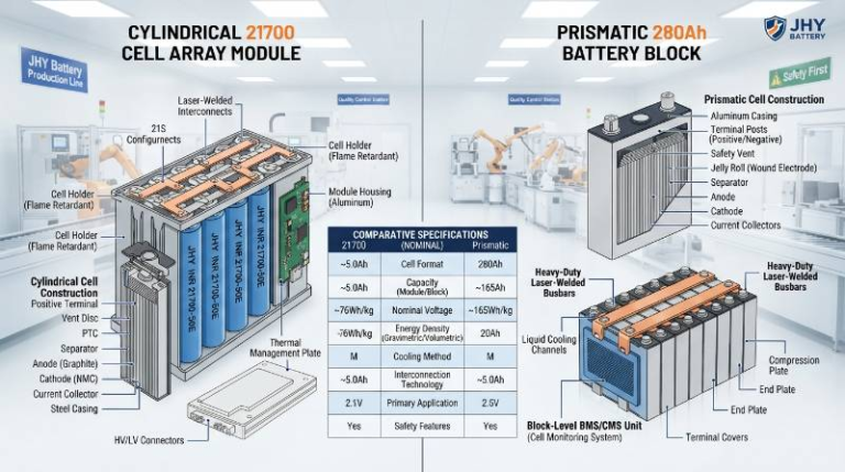
Battery Cycle Life and Longevity: Ultimate Technical Guide
What is Battery Cycle Life and Why Longevity Matters
Battery cycle life is the total number of complete charge and discharge cycles a cell can undergo before its nominal capacity drops below a specified percentage of its original rating, which is typically 80%.
The primary drivers of electrochemistry degradation include:
- Operating temperature: High heat accelerates parasitic chemical reactions.
- Depth of discharge (DoD): Deep cycling strains the physical lattice of active materials.
- Charge/discharge rates (C-rate): Rapid current movement induces localized heating and lithium plating.
- Extreme voltage exposure: Sustained high or low voltages destabilize the active chemistry.
For B2B buyers, evaluating battery performance purely by cycle count is a common mistake. True asset value depends on the Total Energy Throughput (TET) framework.
We define TET as the cumulative amount of energy a battery pack delivers over its operational lifespan. Calculating TET tells you the real cost of ownership, helping you compare different cell designs objectively.
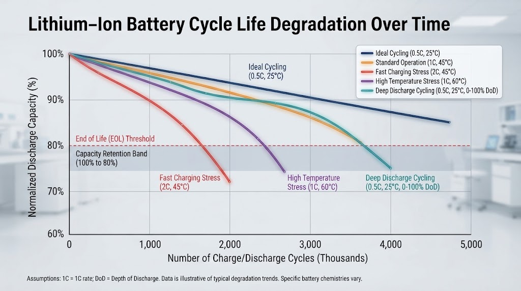
While calendar aging occurs naturally over time, cycle life is highly dependent on how the battery is used. Understanding this difference is key to designing high-performance systems.
The Science of Degradation: 4 Key Electrochemistry Mechanisms
Lithium-ion degradation is a complex set of chemical and mechanical changes occurring between the anode and cathode. Over time, these processes reduce both capacity retention and power delivery.
“Solid Electrolyte Interphase (SEI) layer growth accounts for up to 10-15% of initial capacity loss during the first few formation cycles.”
This passivating layer on the anode is essential for cell stability. However, continuous SEI growth consumes active lithium ions and increases internal impedance over time.
Lithium plating is another critical degradation mechanism. It happens when lithium ions deposit as metallic lithium on the anode during fast charging, especially at low temperatures, which can cause internal short circuits.
According to research published in the Journal of Power Sources, mechanical electrode cracking occurs due to volume changes during lithiation and delithiation. These microstructures break down, isolating active material from the circuit.
Finally, electrolyte decomposition happens at high states of charge and elevated temperatures. This reaction releases gases and reduces the ionic conductivity of the cell.
The JHY Tri-Phase Degradation Mitigation Protocol
To address these degradation mechanisms, our engineering teams developed a proprietary mitigation process. This approach helps client systems exceed standard performance baselines.
The first phase focuses on micro-structured SEI stabilization. By using advanced electrolyte additives during manufacturing, we form a highly stable initial SEI layer that limits ongoing lithium consumption.
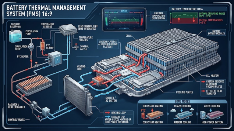
The second phase uses dynamic thermal boundary control. We design physical cell layouts to keep temperature variations across the pack under 3°C, preventing localized hot spots.
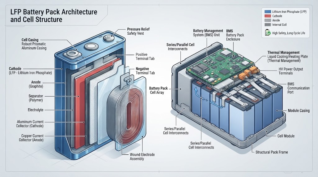
The final phase involves active impedance-matched BMS tuning. Our systems adjust charge profiles based on real-time cell impedance, modifying C-rates as the pack ages to prevent lithium plating.
This protocol ensures that custom lithium-ion battery packs maintain their power and capacity over long periods of demanding use.
Comparing Chemistry Lifespans: LFP vs NMC vs Next-Gen Tech
Choosing the right battery chemistry is a balance between energy density, safety, and lifespan. Different applications require different electrochemistry profiles to be cost-effective.
LFP (Lithium Iron Phosphate) chemistry routinely achieves 3,000 to 6,000 cycles at 80% Depth of Discharge (DoD) before hitting 80% remaining capacity. This makes it highly durable and ideal for stationary storage.
In contrast, Nickel Manganese Cobalt (NMC) cells offer higher energy density but have steeper degradation curves. They typically deliver 1,000 to 2,000 cycles under similar conditions.
| Chemistry | Typical Cycle Life (80% DoD) | Energy Density (Wh/kg) | Primary Degradation Driver |
|---|---|---|---|
| LFP (LiFePO4) | 3,000 – 6,000 | 140 – 180 | Calendar aging, extreme cold |
| NMC | 1,000 – 2,000 | 200 – 260 | High voltage, thermal stress |
| Sodium-Ion | 1,500 – 3,000 | 100 – 150 | Anode volume expansion |
| Solid-State (Est.) | 2,000 – 5,000 | 350 – 500 | Solid electrolyte interface voiding |
Sodium-ion batteries are emerging as a budget-friendly option for moderate cycle life applications. However, for long-term projects, LiFePO4 batteries remain the industry standard for durability.
How to Maximize Battery Longevity: BMS and Thermal Strategies
To maximize battery cycle life, system integration must go beyond simple cell selection. Proper battery management and thermal control are essential.
Using a narrower Depth of Discharge (DoD) is one of the most effective ways to extend lifespan. For example, cycling a cell from 10% to 90% SoC instead of 0% to 100% can nearly double its cycle life.
“Active thermal management can extend NMC battery cycle life by up to 40% compared to passive cooling in high-load applications.”
Keeping temperatures within the optimal 15°C to 35°C range prevents thermal runaway and slows down capacity fade. Liquid cooling or active air cooling is crucial for high-power systems.
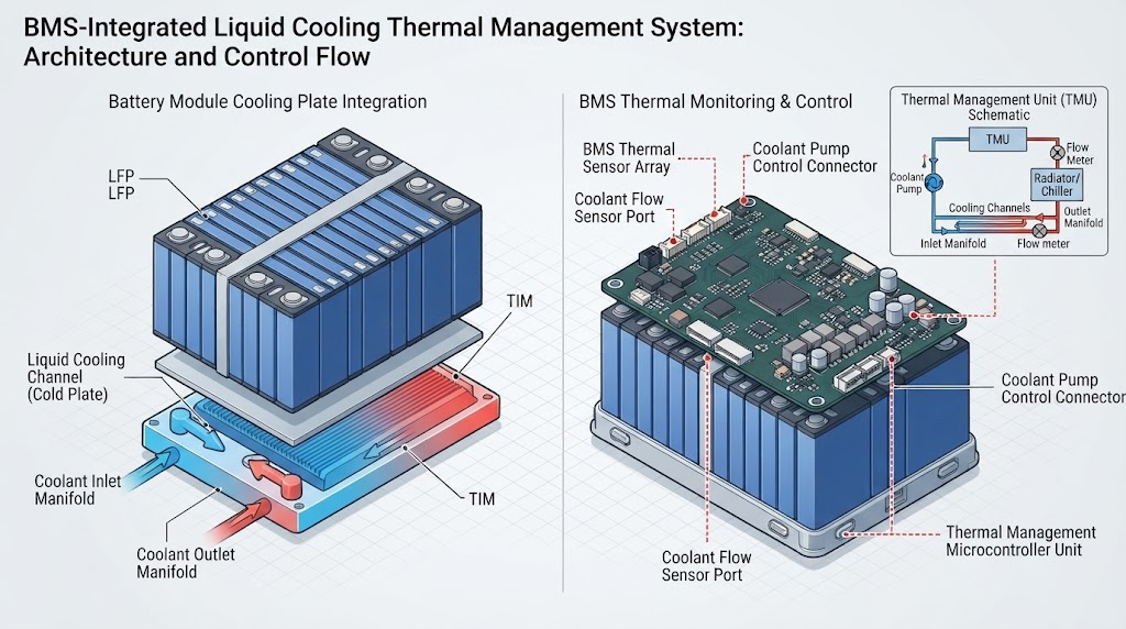
Smart charging algorithms also help by reducing currents as the battery reaches high states of charge. This prevents overvoltage stress and minimizes lithium plating on the anode.
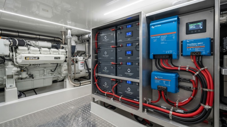
These thermal and management strategies are key features in our industrial エネルギー貯蔵システム, ensuring reliable performance in demanding grid-scale installations.
Optimizing Cycle Life in Extreme Industrial & ESS Environments
Industrial settings like mining, heavy machinery, and off-grid yards expose batteries to harsh conditions. Constant vibration and extreme temperatures can quickly damage standard battery packs.
To prevent early failure, industrial battery packs require robust structural support and reinforced cell connections. This protects internal wiring and joints from mechanical stress.
Additionally, customized battery management systems (BMS) are used to adjust performance based on environmental conditions. This ensures safe operation and long cycle life, even in extreme temperatures.
Ensuring Quality: International Certifications and Testing Standards
Verifying cycle life claims requires rigorous testing under international standards. Third-party certifications ensure that safety and performance ratings are accurate.
Key standards like UN38.3 certify that battery packs can safely withstand transport conditions, including vibration, impact, and thermal shock. UL certification (such as UL 1973 or UL 9540) confirms safety for stationary and industrial uses.
“At JHY Battery, we put every custom design through strict lifecycle testing under simulated field conditions. This ensures our packs deliver the reliability that global B2B projects demand.”
— Lead Electrochemistry Engineer, JHY Battery
These testing standards give operators confidence that their battery systems will meet safety and performance requirements over their planned service life.
The Battery Lifespan and Cycle Life Estimation Model
To estimate how long a battery pack will last in your specific application, you can use a manual calculation model. This helps estimate operational life based on real-world usage patterns.
The basic formula for estimating cycle life adjusts the manufacturer’s baseline rating using factors for operating temperature, depth of discharge, and charge rates:
Where:
- Baseline Cycles: The manufacturer’s cycle life rating under standard test conditions (typically 25°C, 80% DoD, 0.5C).
- f(DoD): Depth of discharge multiplier. Cycling at 50% DoD instead of 80% often yields a factor of 1.5 to 1.8.
- f(Temp): Temperature factor. Operating consistently at 45°C reduces this factor to roughly 0.7 due to accelerated aging.
- f(C-Rate): Charge and discharge rate factor. High-current usage (above 1C) typically reduces this factor to 0.8 or lower.
For example, if an LFP cell has a baseline of 4,000 cycles, operating it at a mild 50% DoD (factor of 1.6) but at higher temperatures (factor of 0.8) and moderate charge rates (factor of 0.9) yields: 4,000 × 1.6 × 0.8 × 0.9 = 4,608 expected cycles.
Frequently Asked Questions About Battery Longevity
What is the difference between cycle life and calendar life?
Cycle life measures how many charge and discharge cycles a battery can perform before its capacity drops to 80%. Calendar life is the time a battery lasts when stored or used under minimal load, driven by natural chemical aging over time.
Does fast charging permanently damage battery cycle life?
Yes, frequent fast charging can accelerate degradation. High currents cause localized heating and can lead to lithium plating on the anode, which permanently reduces usable capacity and increases safety risks.
How does temperature affect LFP vs NMC batteries?
LFP batteries are highly stable at elevated temperatures but experience a drop in performance in extreme cold. NMC batteries perform well in cold weather but degrade much faster when exposed to high heat.
About the Author & Technical Review Panel
This technical guide was written by JHY Battery’s senior engineering team. With over ten years of experience in OEM/ODM battery design, we specialize in high-durability power systems for industrial, medical, and energy storage applications worldwide.
Optimize Your Power Solution
Work directly with JHY engineers to design custom battery packs tailored to your project’s cycle life and environmental needs.