Prismatic vs Cylindrical Battery Cells: Engineering Guide
Prismatic vs Cylindrical Battery Cells: Architectural Trade-Off Matrix
The choice between prismatic and cylindrical cells is fundamentally an engineering optimization balance between volumetric packaging efficiency, thermal heat-rejection vectors, mechanical stress handling, and electrical interconnect topology. Cylindrical formats offer mechanical simplicity and predictable radial thermal paths, whereas prismatic formats eliminate geometric void fractions to maximize pack-level energy density within bounded enclosures.
Selecting the optimal form factor requires evaluating electrical, thermal, and structural system trade-offs rather than comparing single-cell datasheet capacity alone. Integrating large-format prismatic blocks into a mobile chassis introduces cyclic expansion forces that do not occur in cylindrical arrays. Conversely, designing high-voltage strings around small-format cylindrical cells dramatically increases weld counts and multiplies potential points of failure.
At JHY Battery, our engineering teams evaluate these trade-offs through a systematic multi-variable framework developed across three decades of manufacturing custom hardware.
The 6-Dimension Form Factor Selection Matrix (F2SM): A deterministic evaluation method that balances (1) Pack Volumetric & Gravimetric Net Energy Density, (2) Radial vs Planar Thermal Dissipation Paths, (3) Mechanical Breathing Forces vs Canister Rigidity, (4) Interconnect Joint Count & DFM Yield, (5) BMS Topologies and Sensor Granularity, and (6) Lifecycle Tooling Amortization.
Applying the F2SM framework shifts the evaluation from single-cell procurement costs to true total cost of ownership (TCO) and pack-level reliability over 3,000 to 6,000 operational cycles.
Volumetric and Gravimetric Packing Dynamics: Cell-Level vs Pack-Level Realities
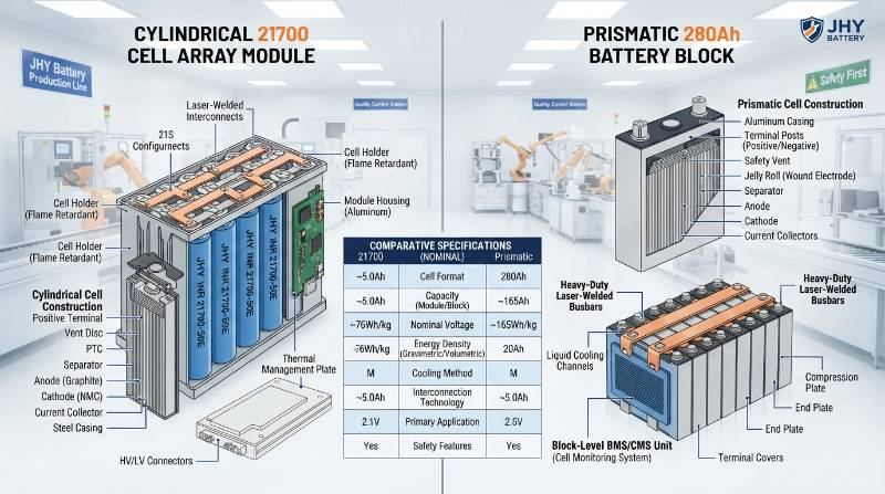
Volumetric space utilization varies widely between cell types and finished battery assemblies. In cylindrical arrays, the theoretical maximum packing density for hexagonal close-packing of equal circles is limited mathematically:
$$\eta_{\text{hex}} = \frac{\pi}{2\sqrt{3}} \approx 90.69\%$$
In actual high-voltage modules, this theoretical density drops significantly. Structural cell holders, thermal gap runners, radial expansion tolerances, and cooling channels reduce the actual volumetric space utilization efficiency to 65%–72%. The interstitial void spaces ($1 – \eta$) represent unusable module volume.
Prismatic cells feature rectangular, rigid aluminum enclosures that eliminate interstitial spatial losses. In modern Cell-to-Pack (CTP) structural configurations, prismatic cells achieve 80% to 85% volumetric utilization efficiency. This eliminates conventional intermediate module side-plates, internal wire harnesses, and distributed carrier frames.
| Metric Parameter | Cylindrical (21700-50E) | Cylindrical (4680) | Prismatic (LFP 280Ah) | Prismatic (NMC 811 100Ah) |
|---|---|---|---|---|
| Nominal Potential (V) | 3.6 V | 3.7 V | 3.2 V | 3.7 V |
| Gravimetric Density (Cell) | 255–270 Wh/kg | 260–280 Wh/kg | 160–180 Wh/kg | 240–260 Wh/kg |
| Pack Volumetric Efficiency | 65%–70% | 72%–76% | 80%–85% (CTP) | 78%–83% (CTP) |
| Effective Pack Density | 165–185 Wh/kg | 190–210 Wh/kg | 135–150 Wh/kg | 195–215 Wh/kg |
| Active Enclosure Material | Nickel-plated Steel | Drawn Steel / Alum. | Alloy 3003 Aluminum | Alloy 3003 Aluminum |
While cylindrical NMC cells provide superior gravimetric density at the cell level, their pack-level volumetric advantage is often offset by thermal margins and mounting structures. For fixed-footprint stationary applications, prismatic LiFePO4 battery packs maximize volumetric energy density ($Wh/L$) without imposing structural weight penalties on immovable balance-of-plant foundations.
Thermal Dissipation Physics: Radial Heat Rejection vs Planar Cold-Plate Architectures
Thermal transport inside spirally wound cylindrical cells is highly anisotropic. Internal heat generated via continuous Joule losses and entropic phase changes travels through distinct conductivities along different coordinate axes:
$$P_{\text{loss}} = I^2 R_{\text{ESR}} + I T \left(\frac{\partial E_0}{\partial T}\right)$$
The spirally wound layers of copper, separator, aluminum, and electrode slurries create substantial boundary resistance. This limits radial thermal conductivity ($k_r$) to $0.2 \text{ to } 1.5 \, \text{W/(m}\cdot\text{K)}$. Conversely, axial thermal conductivity ($k_z$) along the solid copper and aluminum current collector foils reaches $25 \text{ to } 35 \, \text{W/(m}\cdot\text{K)}$.
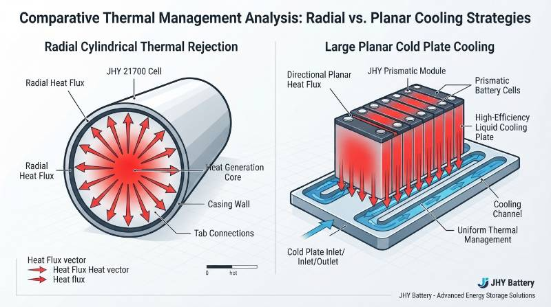
Cylindrical cells (18650, 21700) possess small cross-sectional radii ($r = 9 \text{ to } 10.5 \, \text{mm}$), keeping core-to-surface temperature deltas low ($\Delta T \le 3^\circ\text{C}$ to $5^\circ\text{C}$) during typical continuous 1C discharges. Larger formats, such as 4680 cells, require dedicated tabless continuous-edge foil designs to conduct heat axially toward bottom-mounted cooling assemblies.
Prismatic cells feature broad, planar aluminum side faces. These deliver substantial surface contact area ideal for simple structural cold plates. However, the internal thermal path from the central core of thick 280Ah–314Ah blocks to their outer casing exceeds 35 mm to 40 mm. Under sustained high C-rates, large prismatic cells develop notable internal thermal gradients.
Thermal Runaway Propagation and Passive Safety Barriers
Cell form factor directly dictates thermal runaway dynamics. A standard 21700 cell stores approximately 18 Wh of electrical energy. When pushed to catastrophic thermal runaway during internal short circuits or mechanical penetration, it vents a modest, localized burst of heat and gas.
Cylindrical cells feature mechanical Current Interrupt Devices (CIDs) beneath the positive terminal that decouple under high internal vapor pressure, halting current flow before the separator melts. At the pack level, non-conductive potting compounds or thin aerogel wraps can prevent single-cell failures from cascading to adjacent cells.
In contrast, a 3.2V 314Ah prismatic LiFePO4 cell stores over 1,000 Wh of energy. Under catastrophic failure, the resulting reaction yields violent, high-volume gas deflagration. Prismatic pack architectures mandate directional blast venting, fire-retardant structural barriers compliant with UL 9540A, and high-temperature mica sheets between broad cell faces to arrest thermal propagation across the assembly.
Mechanical Aging and Breathing Management: Clamping Pressures vs Canister Rigidity
Lithium insertion and extraction dynamically alters the lattice parameters of active host materials. In LiFePO4 and silicon-doped graphite electrodes, cycling causes cyclic volumetric expansion—commonly termed “cell breathing”—of 3% to 8% at the electrode stack level.
Cylindrical cells constrain this hoop stress internally using drawn-steel canisters (typically 0.25 to 0.4 mm thick). The circumferential tensile strength of the steel cylinder manages internal radial pressures of 2.0 to 3.0 MPa without needing external structural chassis support.
Prismatic aluminum casings cannot resist these forces unsupported. Unconstrained prismatic cells can bulge and separate along their broad faces over hundreds of cycles. This mechanical separation pulls the active materials away from their current-collector foils, increasing internal resistance (ACIR) and accelerating capacity fade.
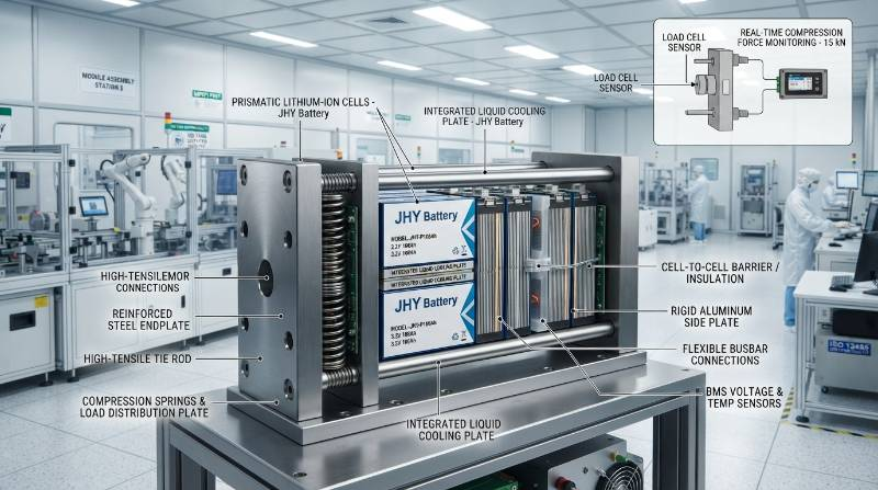
Engineering long-cycle prismatic packs requires mechanical compression fixtures. The mechanical assembly must apply a continuous pre-load pressure:
$$P_{\text{pre-load}} = 0.20 \text{ to } 0.30 \, \text{MPa} \quad (F_{\text{clamping}} \approx 3.5 \text{ to } 6.0 \, \text{kN})$$
Compression frames must feature dynamic spring packs or compliant cellular micro-cellular foam pads. These elements maintain uniform surface pressure without crushing the jelly-roll when the pack reaches high states of charge (SOC) and operational operating temperatures.
DFM, Interconnect Complexity, and Quality Inspection (Wire Bonding vs Busbar Laser Welding)
Production line throughput and operational field reliability depend heavily on electrical interconnect design. Building a 100 kWh battery pack illustrates the contrasting manufacturing footprints of the two cell architectures.
A cylindrical 21700 configuration (nominal 18 Wh/cell) requires roughly 5,500 distinct cells to reach 100 kWh. Using two welded or bonded joints per cell (positive and negative terminals), the completed pack contains over 11,000 interconnect joints. This configuration relies on high-speed ultrasonic aluminum wire bonding or automated spot-welding with micro-fused connections.
A prismatic design based on 3.2V 280Ah cells requires only 112 cells in a standard series-parallel arrangement (e.g., 112S1P). This reduces the main current-carrying joint count to just 112 inter-cell busbar welds. Heavy solid-copper or aluminum busbars are joined using high-precision infrared or green fiber laser welders.
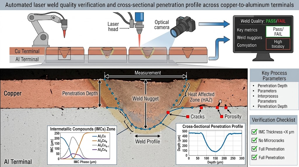
While fewer total welds simplifies pack layout, welding large prismatic terminals requires strict process control. A single poor weld in a series string can interrupt the main current path. At JHY Battery, our automated lines leverage real-time coaxial pyrometry and post-weld Automated Optical Inspection (AOI) to achieve a verified joint defect rate under 0.03% (300 PPM).
Manufacturing Failure Vector (Vibration-Induced Tab Fatigue): High-vibration industrial vehicles subject wire bonds and busbars to mechanical resonance. Cylindrical packs require structural encapsulation via polyurethane potting compounds or rigid injection-molded lattices to suppress bond-wire fatigue. Prismatic interconnects require strain-relief bends within the laminated busbar plates to isolate thermal expansion from terminal studs.
BMS Topologies and Cell Sorting Granularity: High-Parallel vs Series Strings
Electrical topologies dictate the design and architecture of the Battery Management System (BMS). Small cylindrical cells are typically grouped into large parallel blocks before being wired in series (such as a 16S50P configuration). Prismatic systems generally rely on simple, highly observable series strings (such as 16S1P or 16S2P).
Parallel arrays naturally mask individual cell variations. If one 21700 cell develops high internal resistance or an elevated micro-short self-discharge rate, adjacent cells continuously balance current into it. This masks the defective cell from voltage-channel telemetry until the cell overheats or fails. In series prismatic packs, an industrial Analog Front End (AFE) IC monitors every cell directly:
Deploying large prismatic cells requires strict cell screening prior to pack integration. Because each cell directly controls the entire string’s usable capacity, variance between units must be minimized during manufacturing.
| Test Parameter | Sorting Boundary Target | Instrumentation Standard |
|---|---|---|
| Open-Circuit Voltage Match ($\Delta \text{OCV}$) | $\le 3.0 \, \text{mV}$ | 6.5-digit high-resolution DMM |
| AC Internal Resistance ($\Delta \text{ACIR}$) | $\le 0.30 \, \text{m}\Omega$ | 1.0 kHz precision micro-ohmmeter |
| Capacity Verification ($\Delta C$) | $\le 1.0\%$ across batch | Full 1.0C charge / 0.5C discharge baseline |
| Self-Discharge Screening ($K$-value) | $\Delta K \le 0.08 \, \text{mV/day}$ | 14 to 28-day constant-temp rest storage |
Our production facilities maintain comprehensive Manufacturing Execution System (MES) tracking for every cell lot. This ensures full data logging from incoming sorting to end-of-line pack functional validation.
Extreme Niche Engineering: Sub-Zero, High-Vibration, and ISO 13485 Deployments
Standard off-the-shelf battery solutions often underperform or fail when deployed in harsh operating environments. Industrial hardware projects require careful thermal derating and mechanical hardening.
Sub-Zero Thermal Boundaries: Battery systems frequently encounter sub-zero conditions in transport, defense, and high-latitude installations. Operating specifications must clearly separate charge limits from discharge capabilities:
- Standard Charge Window: $0^\circ\text{C} \text{ to } +45^\circ\text{C}$. Attempting to charge standard cells below freezing causes lithium ions to plate as metallic dendrites on the graphite anode, permanently lowering cell capacity and risking internal short circuits. Operating packs down to $-30^\circ\text{C}$ requires integrated PTC or silicone warming blankets to bring core temperatures above $0^\circ\text{C}$ before charge current is enabled.
- Discharge Operating Window: Custom electrolyte formulations allow operational discharge down to $-40^\circ\text{C}$. At these temperatures, cells deliver $\ge 75\%$ rated capacity at 0.2C rates at $-20^\circ\text{C}$, and $\ge 55\%$ at $-40^\circ\text{C}$, avoiding premature low-voltage cutoff events under load.
High-Vibration Environments: In mining machinery and heavy automated guided vehicles (AGVs), unreinforced prismatic cells can experience rapid terminal fatigue. For these operating envelopes, rigid cylindrical configurations assembled with interlocking structural carriers and vibration-absorbing potting compounds can deliver superior mechanical durability.
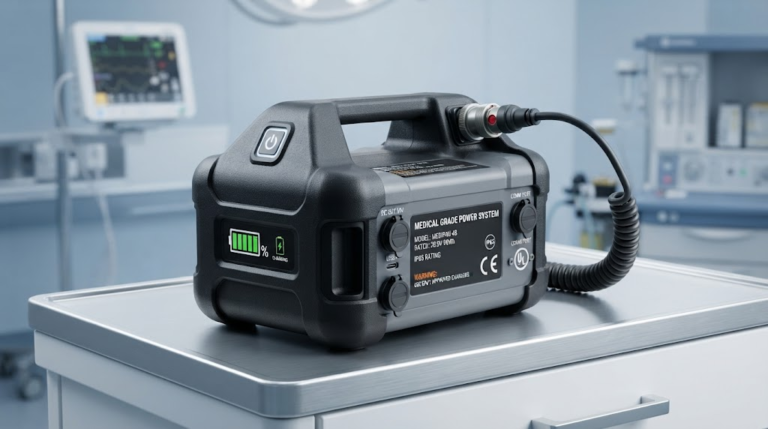
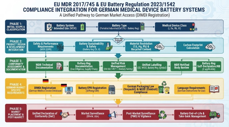
ISO 13485 Certified Medical Deployments: Medical equipment, such as mobile life-support devices and patient monitoring systems, requires deep design redundancy. JHY Battery engineers certified packs to medical device batteries standards, integrating multi-layer safety architectures that include hardware-level overvoltage lockouts, dual secondary-protection fuses, redundant temperature sensors across cells, and hermetically sealed enclosures.
B2B Procurement, CAPEX Tooling Amortization, and Lifecycle TCO Economics
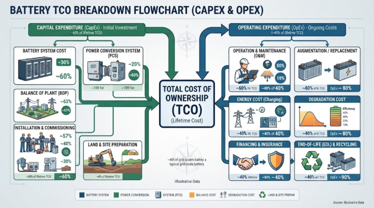
Evaluating form factors from an investment standpoint requires assessing total system lifecycle costs rather than cell-level price per kilowatt-hour ($/kWh) alone. Cylindrical cells benefit from mature, high-volume production, but their total assembly cost must account for plastic holders, complex multi-point busbars, and extended assembly cycle times.
Prismatic cells feature higher initial per-cell costs. However, they reduce total parts count and assembly labor, which typically lowers overall pack production costs in high-capacity systems exceeding 20 kWh.
| Design Parameter | Cylindrical Systems (18650 / 21700) | Prismatic Systems (50Ah – 314Ah) |
|---|---|---|
| Typical End-System Scale | Power tools, medical packs, robotics (<10 kWh) | Industrial C&I, ESS, commercial EVs (>20 kWh) |
| Interconnect Density | High (100–200 weld joints per kWh) | Minimal (1–2 busbar joints per kWh) |
| Compression Fixture | Not required (rigid drawn canister) | Mandatory (0.2–0.3 MPa uniform clamping) |
| Tooling & NRE Investment | Higher mold tooling cost for internal carriers | Lower structural sheet metal framing costs |
| Thermal System Layout | Interleaved wavy cooling pipes or axial cold plates | Planar baseplate chillers with thermal gap pads |
| BMS Monitoring Topology | Parallel group aggregation (coarser visibility) | Direct per-cell channel sensing (high accuracy) |
For large-scale utility and commercial & industrial energy storage systems, prismatic LiFePO4 cells are generally the preferred industry standard. For high-drain portable electronics, surgical instruments, and performance-focused mobility, cylindrical formats remain highly compelling due to their thermal characteristics and structural canisters.
よくある質問
What is the true pack-level volumetric efficiency trade-off between prismatic and cylindrical cells?
While cylindrical cells achieve higher cell-level gravimetric energy density in NMC chemistries (up to 280-300 Wh/kg for 21700 vs 240-260 Wh/kg for prismatic NMC), their interstitial void fraction imposes a 28-35% packing penalty in traditional modules. Prismatic cells eliminate geometry-induced voids, reaching 80-85% pack-level volume utilization in Cell-to-Pack (CTP) designs, compared to 65-72% for cylindrical arrays, making prismatic cells structurally superior for static ESS and spatial enclosures.
How do prismatic and cylindrical cells compare in thermal runaway propagation risk?
Cylindrical cells (18650/21700) possess lower stored energy per unit (10-20 Wh), meaning an isolated single-cell runaway can be arrested using phase-change materials or aerogel barriers to prevent cascade failure. Large prismatic cells (280Ah-314Ah store ~896-1004 Wh each) release immense kinetic and thermal energy upon breach. Prismatic pack architectures mandate directional burst vents, mica/aerogel inter-cell insulation sheets, and cold-plate bottom cooling to prevent catastrophic thermal cascade.
How do you verify genuine Grade-A cell status and matching tolerances for prismatic and cylindrical strings?
Grade-A verification requires automated testing across four non-negotiable parameters: 1) Static OCV drop rate (K-value) measured over 14-28 days (Delta K <= 0.08 mV/day); 2) AC internal resistance sorting at 1 kHz with Delta ACIR <= 0.3 mOhm; 3) Capacity distribution Delta C <= 1.0%; and 4) Factory barcode MES traceability verifying original manufacturer electrochemistry lots without ground-down terminals or relabeled wraps.
Why is mechanical pre-load clamping mandatory for large-format prismatic LiFePO4 cells?
During charge-discharge cycling, lithium intercalation induces a 3% to 8% volumetric expansion (breathing) in prismatic jelly-rolls. Without controlled mechanical compression (3 kN to 5 kN or 0.2 to 0.3 MPa uniform pre-load), delamination of active material from current collector foils occurs, accelerating capacity fade and leading to premature internal micro-shorts. Cylindrical cells constrain this expansion inherently via their rigid drawn-steel canister.
Accelerate Custom Battery Pack Development with JHY Battery
Selecting cell formats, modeling thermal dissipation, and configuring pack architectures requires close collaboration across mechanical, electrical, and manufacturing engineering disciplines. Poor component choices can result in thermal gradients, interconnect fatigue, or unexpected field failures.
JHY Battery (China Battery Manufacturer) provides comprehensive engineering support and production services for custom battery packs. Backed by 30 years of manufacturing experience, our team of 800+ R&D engineers and 400+ production technicians ensures every pack meets stringent performance targets.
Our capabilities include custom system voltages from 3.7V to over 600V, support for cylindrical (18650, 21700, 4680) and prismatic (50Ah to 314Ah+) platforms, complete BMS design and architecture, and compliance certifications including ISO 13485, ISO 9001, UL 1642, UL 1973, IEC 62133-2, CE, and UN38.3. Every build is backed by a verified defect rate under 0.03% (300 PPM).
Turnkey B2B Engineering & Prototyping Path
- Step 1: Application Sizing: Define voltage requirements, continuous and pulse discharge profiles, volumetric envelope constraints, and target ambient conditions.
- Step 2: DFM & Thermal Co-Simulation: Our engineering team conducts CAD layout, interconnect thermal FEA, and BMS architecture design.
- Step 3: Rapid Prototyping: Complete prototype assembly delivered in 5 to 7 business days, accompanied by full factory test reports and UN38.3 transport validation.
Direct Engineering Contacts:
Email: Simple@chinabatterymanufacturer.com | joeshen@chinabatterymanufacturer.com
Direct Phone / WhatsApp: +86-18575997879