How to Optimize Portable Power Station Battery Life
Outdoor portable power stations provide critical off-grid electricity for overlanding expeditions, field research, and residential backup. However, real-world usable watt-hour capacity often falls short of the manufacturer’s rated nameplate capacity due to operating conditions, parasitic loads, and thermal mismanagement.
Optimizing portable power station battery performance requires mastering internal electrochemistry, controlling ambient thermal exposure, and setting disciplined charging protocols. Implementing precision management preserves energy density and extends asset service life for years.
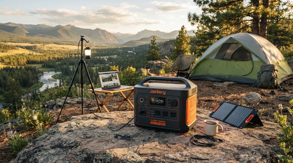
Core Factors That Govern Portable Power Station Battery Health
Optimizing portable power station battery performance relies on managing operating temperatures, depth of discharge, charging current stability, and parasitic idle loads. Maintaining cells between 0°C and 40°C, operating within a 20% to 80% capacity window, utilizing MPPT solar inputs, and disabling idle inverters preserves system health and cell balance.
- Temperature Control: Restrict all charging routines strictly to 32°F–104°F (0°C–40°C).
- Depth of Discharge (DoD) Window: Maintain a daily operating range between 20% and 80% State of Charge (SoC).
- Regulated DC Solar Charging: Prioritize MPPT inputs over unregulated, high-heat AC wall fast-charging.
- Standby Load Shutdown: Turn off internal AC pure sine wave inverters and 12V DC ports when idle.
- Periodic BMS Recalibration: Run a full 0% to 100% cycle every 90 days to eliminate SoC drift.
Watt-Hour Capacity Efficiency: The ratio of actual deliverable electrical energy (measured at output ports under continuous discharge) relative to the theoretical electrochemical capacity rating of the internal battery pack.
Every portable generator relies on a balance between cell chemistry, thermal regulation, and algorithmic oversight from a Battery Management System (BMS). When power stations fail prematurely, the cause is rarely sudden hardware defects. Instead, degradation typically stems from micro-stresses: micro-cycling at high voltage ceilings, persistent parasitic draws, or charging in cold weather.
Chemistry Matters: LiFePO4 vs. Traditional Lithium-ion (NMC/NCA)
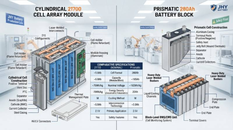
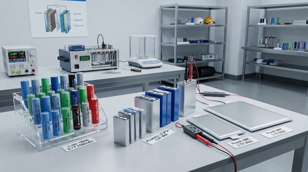
Modern portable power stations generally rely on one of two lithium formulations: Lithium Iron Phosphate (LiFePO4 or LFP) or Lithium Nickel Manganese Cobalt Oxide (NMC). Understanding the distinction is foundational to setting appropriate operational limits.
NMC chemistry offers high gravimetric energy density, making early units from commercial brands like Jackery and older EcoFlow series lightweight and compact. However, NMC cells degrade faster under elevated temperatures and aggressive depths of discharge, averaging 500 to 800 full cycles before dropping below 80% original capacity.
In contrast, LiFePO4 chemistry provides exceptional structural and thermal stability. LFP cells tolerate thousands of cycles and exhibit a much higher thermal runaway threshold (around 270°C compared to 150°C–210°C for NMC). For long-term mobile deployments, choosing custom LiFePO4 battery pack solutions provides the baseline reliability required for demanding industrial and outdoor applications.
| Performance Metric | LiFePO4 (LFP) | Lithium Nickel Manganese Cobalt (NMC) |
|---|---|---|
| Cycle Life (to 80% Capacity) | 3,000 to 5,000+ Cycles | 500 to 800 Cycles |
| Thermal Runaway Threshold | ~270°C (518°F) | ~150°C to 210°C (302°F to 410°F) |
| Energy Density (Wh/kg) | 90 – 160 Wh/kg (Heavier) | 150 – 250 Wh/kg (Lighter) |
| Discharge Voltage Curve | Flat (Stable 3.2V nominal per cell) | Sloped (Gradual drop from 4.2V to 3.0V) |
| Sub-Zero Charging Resilience | Requires active pre-heating | Vulnerable to plating without heat |
The 4-Tier Battery Performance Preservation Protocol (BP3)
To eliminate ambiguity in field operations, our engineering team developed the Battery Performance Preservation Protocol (BP3). This framework provides an operational blueprint for fleet managers, overlanders, and emergency responders looking to optimize lithium systems.
- Tier 1: Thermal Stabilization: Maintaining cell core temperatures strictly between 15°C and 25°C during high-rate charging and preventing charging current activation when ambient conditions fall below 0°C.
- Tier 2: Charge Threshold Gating: Restricting standard cycle depth between 20% and 80% State of Charge (SoC) to minimize mechanical stress on the cathode crystal lattices.
- Tier 3: Parasitic Drain Mitigation: Systematically isolating internal inverter stages, display logic, and RF transceivers to prevent micro-discharges below the low-voltage cutoff.
- Tier 4: Scheduled BMS Recalibration: Performing periodic top-and-bottom balancing runs to reset Coulomb counters and eliminate State of Charge drift.
Thermal Management: Sub-Zero Charging and Extreme Heat Mitigation
Ambient temperature represents the single largest environmental factor dictating lithium cell health. While discharge can safely occur at sub-zero temperatures (down to -20°C with nominal efficiency losses), charging below freezing is hazardous.
“Charging a standard lithium battery below 0°C (32°F) can cause irreversible lithium plating, reducing usable capacity by up to 30% in a single cycle.”
When forced to accept charging current below 0°C, lithium ions cannot intercalate into the graphite or carbon anode quickly enough. Instead, metallic lithium deposits directly onto the anode surface. This lithium plating creates internal dendrites that can pierce separator membranes, causing permanent internal micro-shorts and elevating thermal runaway risks.
In high-end systems, intelligent low-temperature BMS sensors halt incoming current automatically. For sub-zero operations, always run the power station under a moderate discharge load first (such as running a 12V portable fridge or internal thermal heater pad) to raise core pack temperatures above 5°C before connecting solar or AC chargers, as documented in Department of Energy battery research.
Conversely, operating power stations in enclosed, unventilated vehicle cabins where internal temperatures exceed 45°C (113°F) accelerates Solid Electrolyte Interphase (SEI) layer growth. Always position the station in shaded, ventilated breezeways with minimum 4-inch clearances around cooling fan intake and exhaust ports.

Smart Charging Strategies: The 20-80 Rule and Solar MPPT Optimization
Consistently charging a power station to 100% and draining it to 0% creates high mechanical and chemical strain on internal cell electrodes. While occasional full cycles are required for calibration, daily shallow cycling extends asset life.
“Operating LiFePO4 cells within an 80-20% depth of discharge window extends cycle longevity by up to 300% compared to sustained 100-0% cycling.”
When integrating solar arrays for field recharge, always ensure your setup utilizes a Maximum Power Point Tracking (MPPT) charge controller. Unlike rudimentary Pulse Width Modulation (PWM) circuits, MPPT controllers sweep panel voltage and current curves in real time, converting excess input voltage into charging amperage with up to 98% electrical efficiency.
For custom industrial builds and heavy-duty field setups, pairing your array with dedicated custom energy storage systems (ESS) guarantees that input current remains precisely matched to cell acceptance curves, mitigating excessive heat generated by rapid grid chargers.
Avoid using ultra-fast AC grid charging modes (e.g., 0-80% in 45 minutes) unless required for immediate operational needs. High charging rates (above 0.8C to 1C) generate internal heat that accelerates electrolyte decomposition.
Eliminating Parasitic Drain: Inverters, Displays, and Standby Draw
One of the most common user frustrations is turning on a stored power station only to find the capacity depleted. This loss is rarely caused by natural cell self-discharge, which averages just 1% to 2% per month in high-quality LFP packs.
“Inverter standby mode and continuous LCD display active states can account for a 15W to 35W constant parasitic drain, depleting stored energy within 48 to 72 hours.”
Pure sine wave AC inverters require active baseline power to drive internal oscillator circuits, step-up transformers, and cooling logic. Even when zero watts are being drawn by an appliance, keeping the AC master switch turned on consumes continuous power.
Follow these steps to eliminate silent parasitic losses:
- Power Down Inverters: Toggle off AC master switches immediately once power tools or appliances are unplugged.
- Disable Wireless Modems: Turn off persistent Bluetooth, Wi-Fi, and IoT app telemetry features when operating off-grid.
- Configure Display Timeouts: Set LCD backlight timers to the minimum setting (30–60 seconds) rather than “Always On.”
- Isolate 12V Regulators: Keep auxiliary cigarette lighter and Anderson powerpole outputs switched off when not powering DC loads.
Step-by-Step BMS Recalibration and Long-Term Storage Guidelines
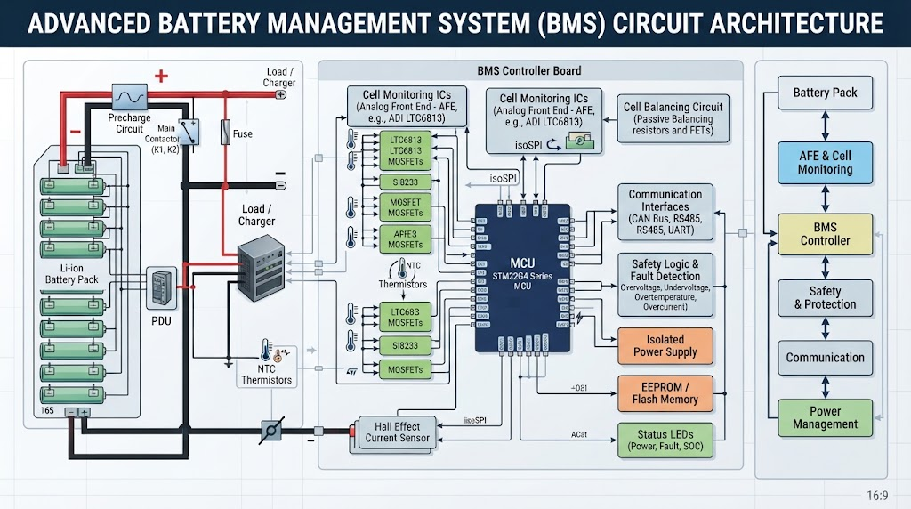
Modern Battery Management Systems calculate remaining battery percentage using Coulomb counting—integrating current flow over time. Over weeks of partial charge-discharge cycles (such as 30% to 70%), mathematical rounding errors cause the display State of Charge (SoC) to drift out of sync with actual cell voltage.
To restore measurement precision and allow the BMS to balance cell strings, execute the following recalibration procedure once every 3 months:
- Full Depletion: Connect a steady, moderate load (such as a 150W lamp or fan) and run the station until the BMS triggers low-voltage automatic system shutdown.
- Rest Period 1: Let the power station sit idle for 30 minutes in a room-temperature environment (20°C–25°C) to allow internal cell voltages to stabilize.
- Uninterrupted Saturation Charge: Plug the unit into a stable AC source and charge continuously to 100%. Do not disconnect the charger the instant it displays 100%; keep it connected for an additional 2 hours so top-balancing circuitry can balance individual cell banks.
- Rest Period 2: Disconnect AC input and allow the pack to rest for 30 minutes. The BMS Coulomb counter is now fully recalibrated against high-voltage and low-voltage cutoff benchmarks.
For seasonal storage (over 30 days), discharge or charge the power station to 50%–60% SoC. Never store a unit at 100% (which accelerates calendar aging) or near 0% (which risks deep cell bricking from background circuitry). Store the unit between 10°C and 25°C in a dry location, and top off the charge every 3 to 6 months.
Industrial Engineering Standards: Selecting and Customizing Reliable Battery Packs
While consumer-grade portable power stations serve basic recreational needs, commercial fleets, medical response vehicles, and industrial operations require power units engineered to strict tolerances.
When selecting or specifying high-performance energy modules, compliance with international safety protocols is essential:
- UN38.3: Mandatory shock, vibration, altitude, and thermal testing for safe transport.
- ISO9001: Certified manufacturing consistency and cell quality control standards.
- UL1973 / UL1642: Structural thermal containment, electrical insulation, and cell safety.
- CE & RoHS: Electromagnetic compatibility and hazardous material restrictions.
Commercial integrators requiring tailored pack architectures, custom voltage rails (12V, 24V, 48V, 72V), or integrated communication protocols (CANBus, RS485, SMBus) should source directly from facilities adhering to strict OEM/ODM battery manufacturing standards to ensure safety and performance matching your exact application.
Frequently Asked Questions
Why Is My Power Station Losing Battery When Turned Off?
Even when you power off external ports, the internal Battery Management System (BMS) continuously draws micro-amperage to monitor individual cell voltages and run safety circuits. Additionally, if internal Bluetooth, Wi-Fi standby modes, or 12V step-down transformers remain engaged, this parasitic draw can deplete 1% to 3% of total battery capacity per day.
Can I Leave My Portable Power Station Plugged into Solar Continuously?
Yes, provided your portable station incorporates an intelligent MPPT charge controller and an overcharge-protected BMS. Once the battery reaches 100% SoC, the BMS cuts off the charging path or transitions to float voltage. However, keeping cells held at 100% capacity in high ambient heat can accelerate calendar aging; maintaining the system around 80% is preferable for long-term stationary use.
About the Technical Reviewer & JHY Battery Engineering Lab
This technical guide was prepared in collaboration with the Senior Engineering Team at JHY Battery (Juheyuan Science & Technology Co., Ltd.). With over a decade of certified leadership in lithium chemistry R&D, JHY Battery specializes in custom lithium-ion battery packs, LiFePO4 energy storage systems (ESS), and industrial power solutions for global B2B partners.
Operating under ISO9001 quality management, JHY Battery delivers turnkey OEM/ODM engineering—tailoring cell geometry, custom BMS communication profiles, and structural enclosures to meet global safety standards including CE, UN38.3, MSDS, and UL.
Need Custom Battery Engineering for Your Product Line?
Partner with JHY Battery for custom LiFePO4 packs, industrial energy storage systems, and turnkey OEM/ODM solutions tailored to your technical specifications.