How to Design Waterproof Marine Battery Enclosures
The 5-Tier Marine Enclosure Integrity Architecture (MEIA)
Designing a waterproof battery enclosure for marine applications requires an integrated electro-mechanical-thermal system capable of surviving continuous cyclic vacuum pumping, dynamic wave impact, and corrosive saltwater bilges. Standard off-the-shelf industrial boxes fail because they treat waterproofing as a static joint rather than a thermodynamic interface. Reliable marine energy systems demand coordinated materials science, precise clamping finite element analysis (FEA), and certified multi-stage safety venting.
In our manufacturing experience across global naval, workboat, and yacht programs, an enclosure cannot be designed as an afterthought around completed cell blocks. It must be engineered using a structured system. We evaluate and manufacture marine enclosures through The 5-Tier Marine Enclosure Integrity Architecture (MEIA):
| Architecture Tier | Engineering Focus | Critical Design Parameter | Validation Protocol |
|---|---|---|---|
| 1. Thermodynamic Pressure | Cyclic Delta-P & Vacuum Elimination | Continuous ePTFE airflow ≥300 ml/min/cm² @ 7 kPa | Rapid thermal shock test (-20°C to +60°C) |
| 2. Elastomeric Stress | Gasket Compression Retention | 25% to 30% squeeze; void volume fill ≤85% | FEA joint deflection & creep analysis |
| 3. Galvanic Metallurgy | Electrochemical Passivation | Anodic index difference ≤0.15V across interfaces | ASTM B117 1,000-hour salt fog exposure |
| 4. Thermal-Mechanical | BMS Dissipation & Cell Retention | Direct conductive thermal paths ≤0.8 K/W resistance | Continuous full-load C-rate thermal imaging |
| 5. Marine Compliance | Naval Type Approvals & Safety | Flame retardant UL 94 V-0; deflagration rupture | ABYC TE-13, E-11, DNV-GL Class A, UN 38.3 |
Applying this framework ensures that engineered custom battery packs survive the dynamic and hostile operating profiles found offshore.
Marine Environmental Stressors: Beyond Static Ingress Ratings
Off-the-shelf industrial battery enclosures rely on the IEC 60529 Ingress Protection Standard. However, passing an IP67 bench test does not guarantee survivability in a marine vessel.
IEC 60529 static testing immerses an unpowered enclosure in a calm freshwater tank at a 1-meter depth for 30 minutes at room temperature. Real maritime service subjects power packs to dynamic, high-stress conditions:
- Dynamic Hydrostatic Heads: Planning hulls, rigid-hull inflatables (RHIBs), and wave-piercing autonomous vessels experience wave impacts exceeding 45 to 80 kPa (6.5 to 11.6 psi). This localized dynamic head easily forces water past standard flat gaskets.
- Saturated Bilge Atmospheres: Marine bilges operate near 100% relative humidity containing atomized oil, fuel hydrocarbons, and saline aerosols that degrade standard commercial neoprene or Nitrile seals.
- Dynamic Wave-Slamming Shock: Multi-axis mechanical shocks exceeding 15g to 25g bend thin enclosure walls, temporarily decoupling gasket contact surfaces and admitting water.
- Salt Deposition and Creep: Evaporation cycles leave hygroscopic salt crystals on joint edges, drawing moisture across seal boundaries via capillary action.
IEC 60529 Definition (IP67 vs. IP68): IP67 indicates protection against water ingress during static immersion up to 1 meter for 30 minutes. IP68 denotes protection during continuous submersion under conditions specified by the manufacturer, typically defined in maritime environments as 2 to 5 meters for 24+ hours under dynamic head pressure.
Enclosure Material Selection: Metallurgical & Structural Trade-offs
Selecting the structural material dictates structural rigidity, thermal dissipation paths, payload mass, and corrosion behavior. The three most common materials in marine systems present clear structural and thermal trade-offs.
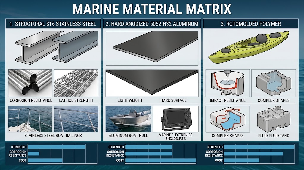
| Engineering Parameter | Marine 316 Stainless Steel | Anodized 5052-H32 Aluminum | Rotomolded HDPE / LLDPE |
|---|---|---|---|
| Density (g/cm³) | 8.00 (High deadweight) | 2.68 (Optimal strength-to-weight) | 0.95 (Ultra-lightweight) |
| Yield Strength (MPa) | 290 | 195 | 20 – 25 |
| Thermal Conductivity (W/m·K) | 16.2 (Poor conduction) | 138 (Excellent heat-sinking) | 0.45 (Thermal insulator) |
| ASTM B117 Rating | >2,000 hrs (Pitting resistant) | 1,000+ hrs (Requires Type III Hardcoat) | Immune to salt degradation |
| Flame Rating | Non-combustible | Non-combustible | Requires UL 94 V-0 flame dopants |
For commercial electric workboats and offshore autonomous vessels, marine-grade 5052-H32 sheet metal or 6061-T6 CNC-machined extrusions deliver an optimal balance of structural strength and thermal management. However, aluminum requires rigorous surface passivation.
We treat all aluminum marine enclosures with a MIL-A-8625 Type III Class 1 Hard Anodize (50 μm thickness), sealed in nickel acetate. This forms an electrically inert, sapphire-hard surface layer (Rockwell C 60) that stops salt fog corrosion and galvanic current paths.
Mitigating Galvanic Corrosion in Harsh Saltwater Environments
Fastener corrosion causes catastrophic seal failure when pairing stainless steel hardware with aluminum housings. Saltwater acts as an aggressive electrolyte, creating an active galvanic cell.
Under marine design guidelines, the galvanic potential delta (anodic index difference) between mating metals exposed to saltwater must not exceed 0.15 V. The potential difference between 316 Stainless Steel (-0.50 V) and 6061-T6 Aluminum (-0.90 V) is 0.40 V—far exceeding the safe threshold.
To eliminate this failure mode without sacrificing fastener shear strength, we implement four strict rules on our assembly lines:
- Non-Conductive Isolation Washers: Fit Delrin (polyoxymethylene) or virgin nylon shoulder washers beneath every 316 stainless steel bolt head and washer to break metallic contact with the chassis.
- Thread Isolation Sleeves: Insert non-conductive sleeves or PTFE heat-shrink tubing over bolt shanks passing through through-hole clearances.
- Passivating Barrier Compounds: Apply fluoropolymer-based anti-corrosion barrier pastes (such as Tef-Gel) to all internal threads to seal microscopic voids against moisture intrusion.
- Sacrificial Zinc/Aluminum Anodes: For pack chassis deployed in continuously flooded bilges or subsea pods, bolt an external MIL-SPEC zinc anode to a dedicated un-anodized, conductive grounding boss.
Gasket Engineering, Joint Profiles, and Clamping Mechanics
Flat gaskets compressed between two flat sheet-metal flanges frequently fail in marine applications. Bolt torque causes the flange to bow between bolt holes, reducing compression at mid-span and creating leak paths.
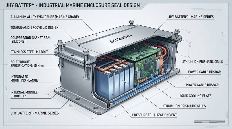
Reliable IP68 ingress protection requires an engineered Tongue-and-Groove or Dovetail O-Ring Channel. This geometry encapsulates the elastomeric seal on three sides, controls squeeze ratios, and blocks lateral extrusion under wave slamming or pressure spikes.
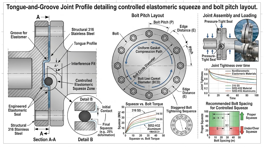
Our tooling and mold specifications enforce four key seal parameters:
- Nominal Gasket Squeeze: Maintain a 25% to 30% squeeze ratio under full clamp load. Compressing under 20% risks fluid bypass across surface roughness; compressing over 35% causes elastomer micro-fracturing and rapid compression set.
- Groove Fill (Void Volume): Restrict maximum elastomer volume to 75% to 85% of total groove void volume. Because elastomers are practically incompressible, overfilling the groove forces the joint open and bends housing flanges.
- Elastomer Formulation: Use Fluorosilicone (FVMQ) or marine-grade EPDM (60 to 70 Shore A durometer). Fluorosilicone provides high resistance to diesel fuel, hydraulic oil mist, ozone, and temperatures from -50°C to +175°C while retaining elasticity.
- Continuous Bolt Pitch Spacing: Calculate maximum bolt spacing using standard beam deflection formulas. Lid deflection between adjacent bolts must never exceed 0.05 mm (0.002 in).
We calculate maximum bolt pitch ($P_{max}$) to eliminate flange bowing:
P_{max} = \sqrt[4]{\frac{384 \cdot E \cdot I \cdot \delta_{allow}}{w}}
Where $E$ represents the Young’s Modulus of the lid material, $I$ is the area moment of inertia of the flange lip cross-section, $\delta_{allow}$ is the maximum permissible deflection (0.05 mm), and $w$ is the target linear clamping load required to maintain the 25% gasket squeeze ratio.
Mechanical Compression vs. Potting Compounds
Engineers often debate whether to use mechanical compression seals or fully encapsulate the interior with potting compound. Both approaches offer distinct trade-offs depending on cell chemistry and operational profiles:
| Evaluation Metric | Precision Gasketed Enclosure | Two-Part Polyurethane/Silicone Potting |
|---|---|---|
| Submersion Reliability | IP67/IP68 verified via air decay testing | True void-free IP68/IP69K absolute barrier |
| Serviceability & Rework | 100% field-serviceable (BMS & cell replacement) | Non-serviceable; destructive disassembly only |
| Weight Penalty | Air-filled cavity; minimum system deadweight | High mass increase (+30% to +50% pack weight) |
| Vibration Dampening | Internal isolation dampers & retention jigs | High shock-absorption matrix |
| Thermal Conductivity | Directed conduction plates to outer casing | 0.8 to 1.2 W/m·K across entire potted block |
For high-capacity propulsion and yacht house banks, mechanical compression seals remain the engineering standard. They allow cell-level maintenance, simplify recertification, and eliminate hundreds of pounds of unnecessary potting mass.
Thermodynamics and Safety Pressure Venting: Managing Delta-P
The primary reason sealed marine battery boxes leak is not hydrostatic depth, but thermodynamic barometric breathing. Enclosing air inside a hermetically sealed box without bidirectional pressure management creates severe pressure deltas.
A vessel operating in tropical conditions (40°C internal ambient) running high-discharge propulsion drives internal cell and busbar temperatures to 55°C. If cold sea spray hits the hull or the bilge floods with 12°C water, the internal air rapidly cools.
Using the ideal gas relation ($\Delta P = \frac{n R \Delta T}{V}$), a sudden 40°C temperature drop creates an internal vacuum of 12 to 16 kPa (1.7 to 2.3 psi). This vacuum pulls moist, salty air—and any standing bilge water—past wire penetrations, connector threads, and gasket seals.
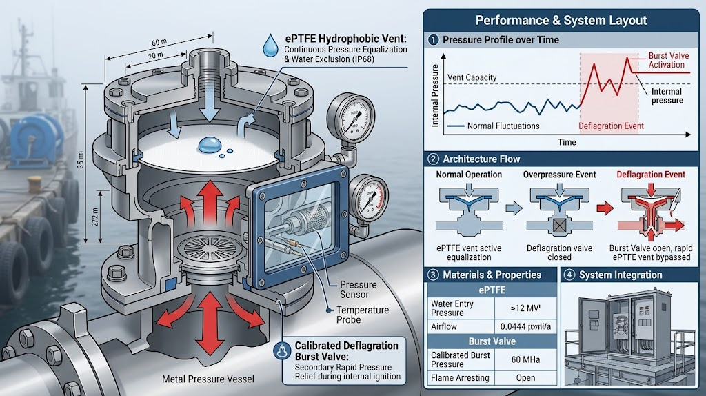
To eliminate vacuum pumping while containing safety hazards, our LiFePO4 battery packs employ a Dual-Stage Pressure Mitigation Architecture:
- Bidirectional Hydrophobic ePTFE Breathing Membrane: A GORE-style expanded polytetrafluoroethylene (ePTFE) vent rated IP68 and IP69K balances daily thermal expansions and contractions. It permits continuous bidirectional airflow (≥300 ml/min/cm² @ 7 kPa) while blocking water, salt crystals, and bilge fluids (water intrusion pressure >60 kPa).
- High-Flow Overpressure Burst Relief: If a cell suffers thermal runaway, gas generation rates (100 to 500 liters/min) rapidly overwhelm micro-porous ePTFE membranes. A spring-loaded poppet valve or calibrated rupture burst disc (cracking pressure 20 to 35 kPa / 2.9 to 5.0 psi) directs explosive deflagration gases safely outside the vessel via hull ducting, preventing housing rupture.
Internal Battery Architecture and Enclosure Thermal Integration
An IP68 waterproof enclosure is sealed from convective external airflow. As a result, heat generated by continuous discharge currents and internal Battery Management System (BMS) power electronics must dissipate via conduction.
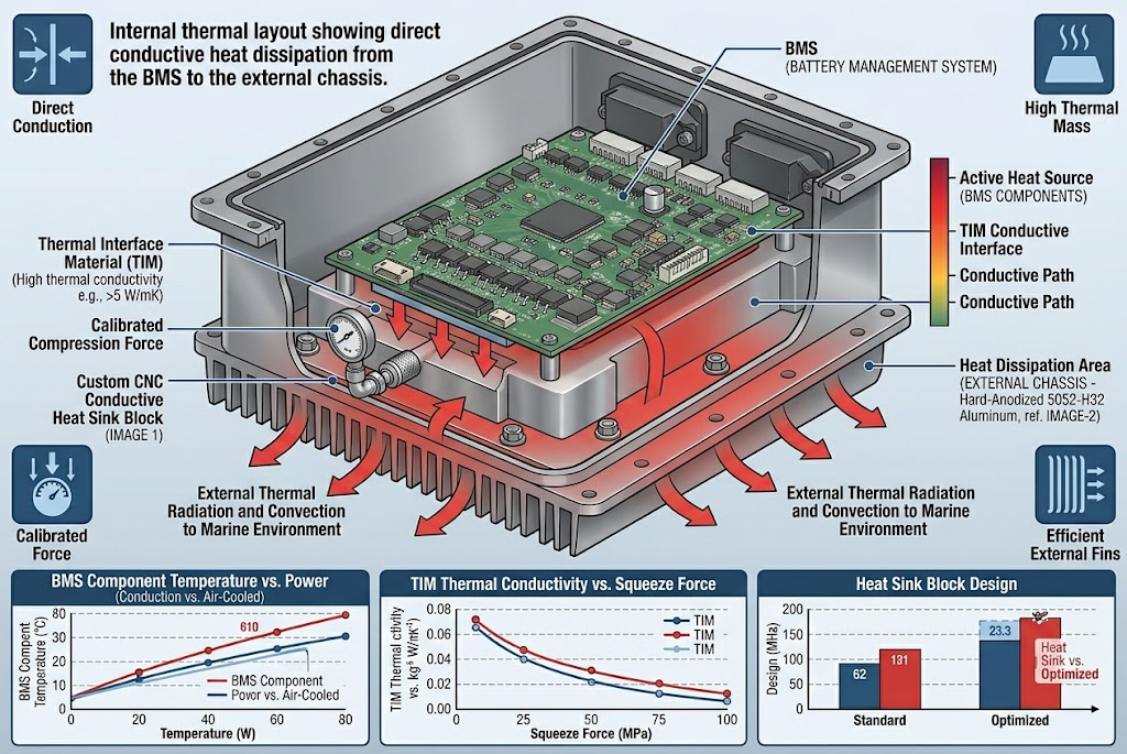
Relying on air convection inside a sealed enclosure causes rapid thermal throttling. Our custom smart BMS design transfers heat using a three-part thermal bus:
- Direct Thermal Interface Coupling: The planar surfaces of high-power BMS MOSFET switches clamp directly to an internal 6061-T6 aluminum heat-spreader bracket using high-performance dielectric gap pads (thermal conductivity ≥6.0 W/m·K, dielectric breakdown >5 kV AC).
- Enclosure Wall Conduction Transfer: This heat spreader bolts flush against the enclosure’s interior wall. The outer surface acts as a broad-surface heat sink, rejecting thermal loads directly to ambient bilge air or surrounding structure.
- Structural Cell Retaining Matrix: Cells must be mechanically isolated from the enclosure shell. We mount prismatic LiFePO4 cells within CNC-machined, flame-retardant (UL 94 V-0) polycarbonate/ABS bracing structures. This layout maintains calibrated compression (300 kgf per prismatic cell stack), accommodates operational cell breathing, and passes UN38.3 shock tests without loading the outer enclosure walls.
High-Current Penetrations, Signal Bulkheads, and Marine Feedthroughs
Every penetration through the enclosure boundary presents a potential ingress point. Standard unsealed terminals and plastic conduit entries fail under dynamic offshore conditions.
We use specific hardware configurations to maintain seal integrity across wall boundaries:
- High-Current Insulated Copper Busbar Feedthroughs: For currents exceeding 150 A, standard cable glands can leak as cable jackets deform under heat. We install nickel-plated copper busbar terminals seated in solid PEEK (polyetheretherketone) or epoxy insulator sleeves, sealed with dual Fluorosilicone O-rings. These handle 500 A continuous loads without cable jacket cold flow.
- Marine Cable Glands (M16 to M32 IP68): Where external cables enter directly, specify marine-grade 316 stainless steel or nickel-plated brass glands with dual-compression elastomer seals and integral wire strain-relief clamps. The internal seal grips the cable sheath while the secondary outer seal blocks salt spray.
- Hermetic Signal and Communication Bulkheads: Route CANBUS, NMEA 2000, RS485, and external sensor wiring through IP68, bayonet-style, multi-pin circular connectors (such as Amphenol SurLok or MIL-DTL-38999 spec). Glass-to-metal sealed contact pins eliminate internal wire wicking.
Regulatory Compliance & Type Approvals: ABYC, DNV-GL, and Lloyd’s
Deploying lithium energy storage aboard commercial or recreational vessels requires adherence to strict naval and marine safety standards.
Enclosure compliance requires certified testing across four core frameworks:
- ABYC TE-13 (Lithium Battery Systems): Mandates that lithium enclosures feature flame-retardant internal components, provide controlled emergency overpressure venting, include moisture ingress barriers, and maintain BMS fault containment without external propagation.
- ABYC E-11 (AC and DC Electrical Systems on Boats): Dictates terminal isolation, positive ignition protection in fuel-adjacent bilges (SAE J1171), and robust conductor strain-relief criteria.
- DNV-GL Class A (Maritime Battery Systems): Requires full system thermal runaway containment testing. The enclosure must vent off-gases directionally away from vessel crew without rupturing or projecting fragments.
- UN 38.3 Transport Certification: The fully assembled enclosure must pass 3-axis vibration testing (10 to 200 Hz sweep) and mechanical shock testing (150g, 6 ms half-sine pulse) without seal loss, structural deflection, or voltage decay.
Our complete systems are manufactured to secure all global battery safety certifications before delivery.
Extreme Marine Niche: Semi-Submerged Bilges and Autonomous Surface Vessels
Standard IP65 off-the-shelf plastic utility boxes quickly fail when installed in demanding environments like unventilated workboat bilges or Autonomous Surface Vessels (ASVs). Continuous exposure to oily bilge water, high mechanical vibration, and wide thermal swings quickly compromises simple seals.
Autonomous surface vessels operate at sea for months without human oversight. Hull slamming continuously flexes standard structural casings, working fasteners loose and admitting moisture.
To eliminate these field failures, JHY Battery builds custom marine assemblies around high-reliability standards:
- Heavy-gauge, CNC-machined 5052-H32 aluminum enclosures with integrated cooling fins and dual tongue-and-groove seals.
- Helium mass-spectrometer testing to guarantee hermetic joint sealing.
- Redundant, optoisolated solid-state BMS controllers that continuously monitor internal relative humidity and insulation resistance.
- Directional venting valves connected to external vessel exhaust manifolds to ensure complete passenger safety.
JHY Battery Manufacturing Standards and Leak-Testing Protocols
Precision mechanical designs depend entirely on consistent production execution. JHY Battery operates state-of-the-art battery integration facilities, supported by deep industrial expertise:
- Engineering Capacity: Over 30 years of industrial electrochemistry and mechanical engineering expertise, supported by 1,200+ team members, including 800+ dedicated R&D engineers.
- Quality Standards: A guaranteed 0.03% (300 PPM) defect rate, maintained through fully automated MES cell sorting, impedance balancing, and complete process traceability.
- Certifications: Dual ISO 9001 and ISO 13485 medical device quality-management systems, alongside full certifications for UL 1642, UL 2054, CE, IEC 62133-2, and UN 38.3.
We do not rely on destructive water dipping to verify seal integrity. Every production enclosure undergoes automated pressure testing on our lines:
- Differential Air Decay Testing: The enclosure is pressurized to 20 kPa (2.9 psi). Pressure drop is measured across a 60-second window at 1 Pa resolution to confirm seal integrity before cell population.
- Helium Mass Spectrometer Sniffing: For critical IP68 subsea and marine propulsion contracts, enclosures undergo tracer gas helium testing. This protocol detects leak rates down to $1 \times 10^{-6}\text{ mbar}\cdot\text{L/s}$, ensuring zero moisture intrusion across years of deployment.
Explore our turnkey capabilities for your next program through our OEM/ODM battery turnkey manufacturing services.
Frequently Asked Questions (FAQ)
Marine 316 Stainless Steel vs 5052-H32 Hard Anodized Aluminum: Which is superior for marine battery packs?
Marine 316 Stainless Steel offers superior galvanic passivity and chemical resistance in acidic bilges but carries a severe weight penalty (density 8.0 g/cm³) and poor thermal conductivity (~16 W/m·K), limiting passive BMS cooling. Marine-grade 5052-H32 or 6061-T6 aluminum with Mil-A-8625 Type III Hard Anodize (50 μm depth) provides exceptional strength-to-weight ratio (density 2.7 g/cm³) and superior thermal conductivity (138 to 167 W/m·K) for conductive heat extraction, provided all stainless steel hardware is isolated using non-conductive Delrin/nylon shoulder washers to eliminate galvanic corrosion.
Mechanical compression gaskets vs complete potting compounds: What are the engineering trade-offs?
Potting (polyurethane or silicone) guarantees absolute IP68 void-free submersion and extreme shock dampening, but renders the battery pack permanently non-serviceable, adds massive thermal mass and dead weight, and complicates UN38.3 shipping certification rework. Precision tongue-and-groove mechanical gaskets (Fluorosilicone or EPDM with 25% to 30% squeeze) allow full serviceability, lower pack weight, and simpler cell-level maintenance, but require strict finite element structural calculations of lid stiffness and bolt pitch to prevent localized seal deflection.
How do you verify waterproof enclosure integrity on the production line without destructive water immersion?
Production enclosures must undergo differential air decay pressure testing or helium mass spectrometer leak testing. Differential air decay pressurizes the sealed enclosure to 15 to 20 kPa (2.2 to 2.9 psi) and measures pressure drops down to 1 Pa resolution over a 60-second stabilization window. For mission-critical IP68 ratings, tracer gas helium sniffing detects leak rates below $1 \times 10^{-6}\text{ mbar}\cdot\text{L/s}$, verifying joint integrity without introducing moisture into delicate lithium cell matrices.
What documentation and audit criteria confirm compliance with ABYC TE-13 and ABYC E-11 for lithium marine battery enclosures?
Compliance requires certified test reports showing: (1) flame retardancy meeting UL 94 V-0 for all non-metallic enclosure components, (2) enclosure containment or controlled directional venting under thermal runaway propagation testing, (3) mechanical shock and vibration compliance per UN38.3 and ABYC TE-13 Section 13.5 drop-test protocols, and (4) terminal isolation capable of withstanding 500V DC insulation resistance testing (>100 Megaohms) after ASTM B117 salt fog conditioning.
From Concept to Sea Trials: 3-Step Custom Marine Enclosure Prototyping
Transitioning from initial CAD concepts to sea-trial-ready hardware requires rigorous engineering verification. We follow a proven three-step design and manufacturing sequence:
- Step 1: Engineering Requirements Definition: Complete spatial CAD packaging, thermal budget mapping, system voltage and capacity definition, IP ingress target (IP67 or IP68 depth profile), and ABYC/DNV regulatory review.
- Step 2: DFM Analysis & Joint FEA Simulation: Run finite element analysis for gasket squeeze retention, optimize bolt pitch to eliminate lid deflection, select barrier materials to prevent galvanic coupling, and configure dual-stage ePTFE safety venting.
- Step 3: Rapid Prototyping & Turnkey Validation: Deliver fully populated, functional CNC/cast enclosure prototypes in 5 to 7 business days, backed by air decay pressure testing, thermal imaging, and UN38.3 vibration pre-scanning.
Request a Custom Marine Battery Enclosure Engineering Consultation
Collaborate with senior marine battery architects on your custom mechanical, thermal, and electrical packaging requirements.
Request Custom Battery Consultation & Prototype Quote
Direct Engineering Lines: Simple@chinabatterymanufacturer.com | joeshen@chinabatterymanufacturer.com | WhatsApp: +86-18575997879