LiFePO4 Solar Batteries Upgrade Australia: B2B Retrofits
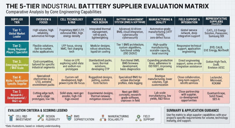
The 5-Tier Australian Solar Storage Retrofit Matrix (ASSRM)
The ASSRM Framework: An empirical qualification standard evaluating Thermal Boundary Index (calendar degradation at 55°C), Standards Compliance Score (AS/NZS 5139 and AS/NZS 4777.2), Inverter Telemetry Integration (closed-loop serial bus handshakes), Electrochemical Cell Integrity (laser-welded Grade-A prismatic cores), and Levelized Cost of Storage throughput ($/kWh over verified cycle life).
| ASSRM Dimension | Legacy Lead-Acid (AGM/Gel) | Residential NMC Packs | JHY Battery Industrial LiFePO4 |
|---|---|---|---|
| 1. Thermal Boundary | Halves lifespan per 10°C rise over 25°C | Thermal runaway initiation at ~150°C | Thermal stability up to 270°C; operates to 55°C |
| 2. Standards Compliance | Acid venting hazards; AS/NZS 5139 restricted | Stringent Class 1 explosion separation rules | IEC 62619, UL 1973, AS/NZS 5139 Level 1 certified |
| 3. Telemetry Integration | Open-loop voltage sensing only; high drift | Proprietary closed CANbus (locked ecosystem) | Multi-protocol CANbus/RS485 auto-addressing |
| 4. Electrochemical Core | Heavy spongy lead plates; sulfation failure | Pouch/cylindrical NMC; dendrite risk | Automotive Grade-A prismatic LFP; busbar-welded |
| 5. Lifecycle LCOS | >$0.32 AUD per delivered kWh | ~$0.18 AUD per delivered kWh | $0.06–$0.09 AUD per delivered kWh |
Deploying energy storage without evaluating these five parameters often leads to premature capacity loss, communication failure with existing inverters, and non-compliance with Australian fire and building codes. For engineered upgrades, visit our dedicated LiFePO4 battery systems documentation.
Thermal Engineering: Operating at 50°C Without Thermal Runaway
Ambient ground temperatures across regional Western Australia, inland New South Wales, and Queensland routinely exceed 45°C during summer, with enclosure internal temperatures reaching 55°C to 60°C. In these environments, cell chemistry selection dictates both operational safety and calendar aging.
LiFePO4 features an ordered olivine-type crystal structure (space group Pnma) with covalent phosphorus-oxygen (P-O) bonds. These bonds possess significantly higher binding energy than the metal-oxygen layers found in NMC or lithium cobalt oxide (LCO) formulations. The exothermic runaway initiation temperature for LiFePO4 sits at approximately 270°C, compared to 150°C for NMC chemistries.
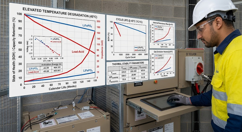
When an LFP cell is pushed past its thermal breakdown threshold, it does not release free elemental oxygen. This prevents self-sustaining fire propagation even during extreme internal mechanical puncture or overcharge conditions. In contrast, lead-acid systems enter thermal runaway via dry-out and oxygen recombination cycles, halving battery calendar life for every 10°C increase above 25°C per Arrhenius modeling.
To support high-temperature off-grid mine sites, agricultural homestead microgrids, and remote telecom repeaters across Australia, JHY Battery houses its cells within IP65/IP66 powder-coated aluminum enclosures designed with natural convective airflow paths, eliminating failure-prone external active cooling fans.
Regulatory Compliance: AS/NZS 5139:2019 & AS/NZS 4777.2:2020
Australian electrical contractors and engineering, procurement, and construction (EPC) firms operate under some of the world’s strictest electrical safety mandates. Clean Energy Council (CEC) accreditation and local distribution network service provider (DNSP) approvals require strict adherence to AS/NZS 5139:2019 and AS/NZS 4777.2:2020.
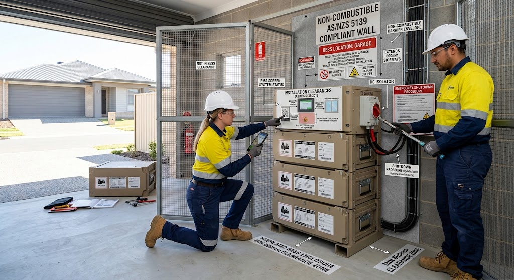
AS/NZS 5139:2019 Battery System Placement Envelopes
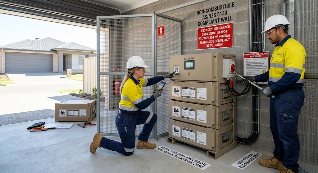
Standard AS/NZS 5139:2019 establishes rigorous zoning rules to mitigate fire propagation risks in residential installations:
- Prohibited Zones: Battery systems classified as Hazard Level 2 or higher must not be installed in habitable rooms, ceiling spaces, wall cavities, under stairs, or directly within designated building escape routes.
- Non-Combustible Barriers: When an ESS is mounted on an external wall with a habitable room on the opposing side, a non-combustible fire barrier (such as brick, masonry, or certified compressed cement fiber sheeting) must extend 600 mm on both sides and 900 mm above the battery enclosure.
- Clearance Offsets: Maintain a strict 600 mm lateral separation from windows, doors, air-conditioning compressors, and mechanical exhaust paths.
AS/NZS 4777.2:2020 Inverter Power Quality Modes
Grid-tied battery retrofits interacting with the National Electricity Market must support dynamic inverter-response behaviors:
- Volt-Watt & Volt-Var Response: The battery-inverter system must modulate active and reactive power output based on real-time grid terminal voltage swings to stabilize local distribution feeders.
- CEC Accreditation: To secure Small-scale Technology Certificates (STCs) and state battery incentives, retrofitted battery modules must be certified to IEC 62619 and listed on the official Clean Energy Council approved battery database.
System Architecture: AC-Coupled vs. DC-Coupled Retrofit Topologies
When upgrading an existing residential or commercial solar array, engineers must decide between an AC-coupled storage retrofit and a DC-coupled hybrid inverter replacement.
| Metric | AC-Coupled Retrofit | DC-Coupled Hybrid Retrofit |
|---|---|---|
| Installation Disruption | Minimal. Leaves existing string solar inverter untouched. | Moderate. Requires replacing the existing solar inverter. |
| Round-Trip Efficiency (RTE) | 85%–88% (Double DC-AC-DC conversion losses) | 92%–95% (Direct solar MPPT-to-battery charging) |
| Blackout Protection | Requires specialized frequency-shifting AC islanding. | Seamless integrated UPS transfer (<10 ms). |
| Best Applied To | Modern, functional existing solar string inverters. | Aging inverters (>7 yrs) or new high-capacity expansions. |
DC-DC Isolation & Vibration Engineering for Outback Mobile Solar
In mobile commercial trailers, outback exploration rigs, and transportable solar generator skids, standard stationary mountings often fail due to severe harmonic vibration on unpaved roads. Furthermore, connecting low-impedance LiFePO4 packs directly to factory vehicle alternators quickly overheats and burns out stator windings, because LFP cells draw maximum charge currents across their entire state-of-charge spectrum.
Engineered mobile upgrades require dedicated DC-DC multi-stage isolated chargers paired with structural pack dampening. JHY Battery integrates laser-welded busbars rather than threaded nut-and-stud terminals, preventing terminal loosening and arcing under continuous vibration. For custom industrial form factors, consult our team regarding custom battery pack engineering.
Smart BMS Integration: Closed-Loop Telemetry vs. Open-Loop Voltage Monitoring
A primary cause of premature battery lockout in Australian retrofits is reliance on open-loop, voltage-based charge tracking. LiFePO4 chemistry exhibits an extremely flat open-circuit voltage curve: the cell voltage plateau rests near 3.28V to 3.32V per cell across 20% to 90% State of Charge (SOC).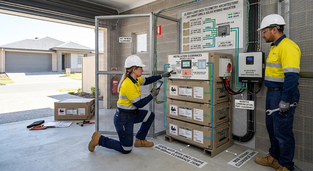 An open-loop inverter attempting to estimate capacity solely from battery voltage cannot detect fine SOC changes, leading to sudden low-voltage cutoff trips during high surge loads. Closed-loop CANbus or RS485 communication eliminates this ambiguity.
Our proprietary Smart BMS firmware delivers high-precision coulomb counting and communicates directly with industry-standard hybrid inverters, including Victron Energy (VE.Can), Deye, SunSynk, SMA, GoodWe, Selectronic, and Solis. The battery dynamically reports:
- Real-time Charge Voltage Limit (CVL) and Discharge Voltage Limit (DVL).
- Maximum continuous Charge Current Limit (CCL) and Discharge Current Limit (DCL), modulated by internal cell temperature extrema.
- Individual cell health metrics, State of Health (SOH), and balance requests.
Learn more about our communication architectures by exploring our smart BMS design and communication protocols.
Cell-Level Construction: Prismatic Grade-A vs. Refurbished Cores
The Australian renewable energy market has seen an influx of low-cost battery packs containing Grade-B or retired secondary-market cells extracted from electric vehicles. These cells degrade quickly under the heavy cycling demands of residential solar.
Every cell batch handled at JHY Battery is tracked through an automated Manufacturing Execution System (MES) down to individual 2D DataMatrix QR codes, maintaining full traceability back to raw foil slitting and electrolyte filling. This engineering discipline underpins our guaranteed field defect rate below 300 PPM (0.03%).
Levelized Cost of Storage (LCOS) Economics: Replacing Legacy Packs
When assessing solar battery upgrades, upfront capital expenditure (CAPEX) offers an incomplete financial picture. Commercial and residential buyers should evaluate Levelized Cost of Storage (LCOS)—the total lifetime cost divided by cumulative usable energy throughput.
The standard LCOS calculation formula is:
LCOS ($/kWh) = (Total Initial CAPEX + Lifetime OPEX) / (Total Usable Capacity × Cycle Life × Round-Trip Efficiency)
| Cost Factor | Deep-Cycle AGM Lead-Acid | Residential NMC Pack | JHY Battery Industrial LiFePO4 |
|---|---|---|---|
| Initial Battery CAPEX | $2,800 AUD | $6,500 AUD | $3,600 AUD |
| Recommended Max DoD | 50% (5 kWh usable) | 85% (8.5 kWh usable) | 90% (9.0 kWh usable) |
| Expected Cycles to 80% SOH | 800 cycles (~2.5 years) | 2,500 cycles (~7 years) | 6,000+ cycles (>15 years) |
| Replacements in 10 Years | 3 replacements | 1 replacement | 0 replacements |
| Total 10-Year Outlay | $11,200 AUD + labor | $11,500 AUD + labor | $3,600 AUD total |
| Estimated LCOS ($/kWh) | ~$0.34 AUD | ~$0.19 AUD | $0.07 AUD |
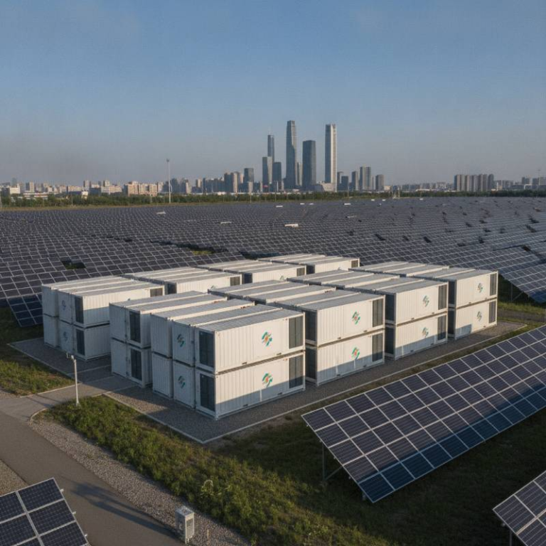
With feed-in tariffs hovering below 5 cents, self-consuming excess rooftop solar generation delivers up to 40 cents per kilowatt-hour in displaced grid electricity costs. At an LCOS of roughly 7 cents, a LiFePO4 upgrade pays for itself within 3.5 to 5 years, providing clean, lower-cost power for its remaining lifespan. For larger projects, see our commercial & industrial energy storage systems.
JHY Battery Industrial Solar Retrofit Specifications
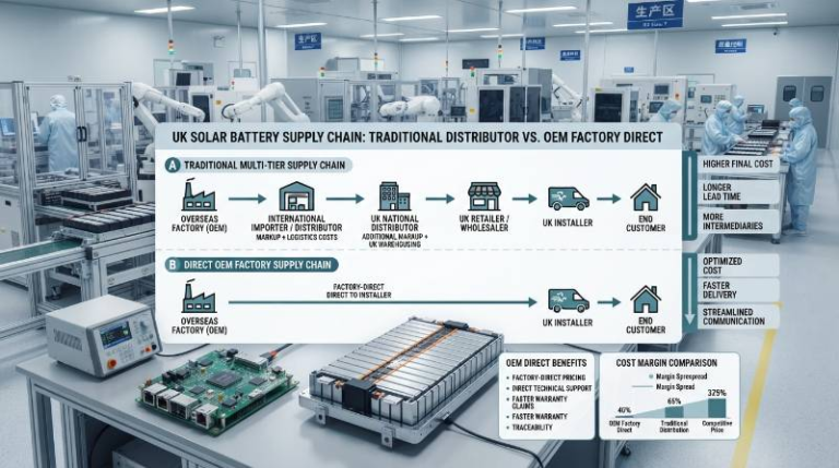
JHY Battery manufactures modular rack-mounted and wall-hung battery packs designed for straightforward retrofits into Australian residential and light-commercial installations.
| Parameter | JHY-ES-51100 (5.12 kWh) | JHY-ES-51200 (10.24 kWh) | JHY-ES-51314 (16.07 kWh) |
|---|---|---|---|
| Nominal Voltage / Capacity | 51.2V / 100Ah | 51.2V / 200Ah | 51.2V / 314Ah |
| Cell Chemistry & Architecture | Grade-A Prismatic LFP (16S1P) | Grade-A Prismatic LFP (16S1P) | Grade-A Prismatic LFP (16S1P) |
| Cycle Life (80% DoD, 25°C) | >6,000 cycles | >6,000 cycles | >6,000 cycles |
| Max Continuous Charge/Discharge | 100A / 100A (1.0C peak) | 150A / 150A (0.75C) | 200A / 200A (0.63C) |
| Communication Protocols | CANbus, RS485, RS232 | CANbus, RS485, RS232 | CANbus, RS485, RS232 |
| Operating Temperature Range | Charge: 0~55°C | Discharge: -20~60°C | Charge: 0~55°C | Discharge: -20~60°C | Charge: 0~55°C | Discharge: -20~60°C |
| Parallel Scalability | Up to 15 packs (76.8 kWh) | Up to 15 packs (153.6 kWh) | Up to 15 packs (241 kWh) |
| Compliance Certifications | IEC 62619, UL 1973, UN38.3, CE | IEC 62619, UL 1973, UN38.3, CE | IEC 62619, UL 1973, UN38.3, CE |
Our OEM/ODM manufacturing capability extends from standard 19-inch rack enclosures to IP66 custom outdoor modular stacks. Explore our full capabilities in turnkey OEM/ODM battery manufacturing.
Technical Verification & Retrofit Engineering FAQ
Execute Your Solar Storage Retrofit: 3-Step B2B Action Path with JHY Battery
To streamline engineering qualification, prototyping, and large-scale delivery for Australian renewable integrators, JHY Battery provides a structured engineering onboarding path:
The 3-Step Action Funnel
- Step 1: Engineering Assessment & Retrofit Sizing: Submit current solar array capacity, inverter model, daily load profile, and physical enclosure constraints to receive a tailored ASSRM capacity and thermal sizing assessment.
- Step 2: DFM Review & Inverter Protocol Verification: JHY Battery application engineers map CANbus/RS485 baud rates and pinout pin-assignments, provide 3D mechanical CAD models, and optimize thermal enclosure design.
- Step 3: Rapid Prototyping & Direct B2B Supply: Receive custom engineering sample battery packs within 5 to 7 business days, accompanied by full UN38.3, IEC 62619 documentation, and direct factory engineering support.
Partner with JHY Battery: Engineering Excellence
Backed by over 30 years of industrial electrochemistry heritage, 1,200+ team members, and 800+ dedicated R&D engineers. JHY Battery guarantees a defect rate below 300 PPM (0.03%) with automated MES quality traceability across every cell.
Request Custom Battery Consultation & Prototype Quote
Direct Inquiries: Simple@chinabatterymanufacturer.com | joeshen@chinabatterymanufacturer.com
Direct Mobile / WhatsApp: +86-18575997879