BMS CAN Protocol Specification: Custom Pack Guide
Architectural Overview of BMS CAN Communication in Custom Lithium Packs
A robust Controller Area Network (CAN) protocol specification serves as the mission-critical nervous system linking internal battery chemistry to the host power plant, motor inverter, or microgrid controller. In mission-critical deployments involving custom lithium battery packs, communication integrity directly governs operational safety, thermal equilibrium, and dynamic power performance.
Modern battery management systems operate within hostile electromagnetic environments characterized by high-voltage common-mode transients (dV/dt) from fast-switching silicon carbide (SiC) and gallium nitride (GaN) power stages. Inadequate CAN bus protocol definitions lead to frame arbitration starvation, buffer overflows, undetected CRC errors, and uncommanded contactor openings during transient load conditions.
At JHY Battery, our battery systems architecture enforces strict physical and logical decoupling between internal cell telemetry sensing and external vehicle or grid-level communications. This guide details the 15 definitive Request for Quotation (RFQ) engineering requirements required to design, validate, and manufacture production-grade BMS CAN architectures.
The 5-Tier Industrial CAN Bus Communication Robustness Matrix
To eliminate protocol ambiguity during the engineering specification phase, BMS integrations should be evaluated against an empirical reliability index. JHY Battery designs custom packs across five definitive engineering vectors to ensure zero communication dropouts over the design life of the system.
| Robustness Dimension | Tier 1: Consumer / Light Duty | Tier 2: Industrial Commercial | Tier 3: Mission-Critical Powertrain / ESS |
|---|---|---|---|
| Galvanic Isolation & CMTI | Non-isolated; common chassis ground | 1.5kV RMS opto-isolation; CMTI < 25kV/µs | 2.5kV to 5kV RMS reinforced digital capacitive isolation; CMTI ≥ 100kV/µs |
| Peak Bus Load Ceiling | > 70% (unregulated broadcast rates) | 50% to 60% dynamic load | ≤ 35% nominal; ≤ 45% during dynamic burst/fault modes |
| Fault Escalation Response | Polling-based; > 250ms cutoff | Heartbeat timeout; 100ms cutoff | Hardware interrupt-driven; deterministic ≤ 10ms trip; rolling counter fault tracking |
| State-of-Charge Tracking | Static OCV lookup table | Standard Coulomb counting without temperature trim | Dual Extended Kalman Filtering (EKF) with dynamic covariance scaling & real-time internal impedance feedback |
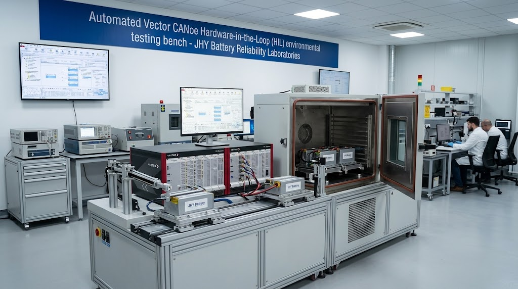
| Specification & Validation | Informal PDF documentation | Standard DBC file; physical bench test | Vector CANdb++ syntactically verified DBC, automated 100% Vector CANoe HIL validation with fault injection |
Engineering robust communication begins at Tier 3 for all our mission-critical intelligent BMS design and engineering projects. Tier 3 prevents costly field recalibrations and high-voltage inverter communication lockouts.
Physical Layer Implementation: Galvanic Isolation, Transceivers, and EMI Hardening
The physical layer (PHY) forms the foundation of CAN bus operational reliability under severe electromagnetic interference (EMI). Industrial battery packs operate adjacent to variable-frequency motor drives and bi-directional inverters that induce continuous ground potential shifts and severe common-mode noise.
Compliance with ISO 11898-2 is mandatory. The transceiver circuitry must decouple the high-voltage battery domain (300V to 1000V DC) from the low-voltage host vehicle controller (12V/24V chassis logic). High-speed reinforced digital isolators (such as the Texas Instruments ISO1042 or Analog Devices ADM3055E) provide dielectric withstand capabilities tested up to 5000V RMS for 60 seconds.
Common-Mode Transient Immunity (CMTI): The maximum tolerable rate of ground potential rise or fall between isolated grounds without inducing logical bit errors on the differential data bus, expressed in kV/µs or V/ns. Industrial inverter interfaces require CMTI ≥ 100kV/µs.
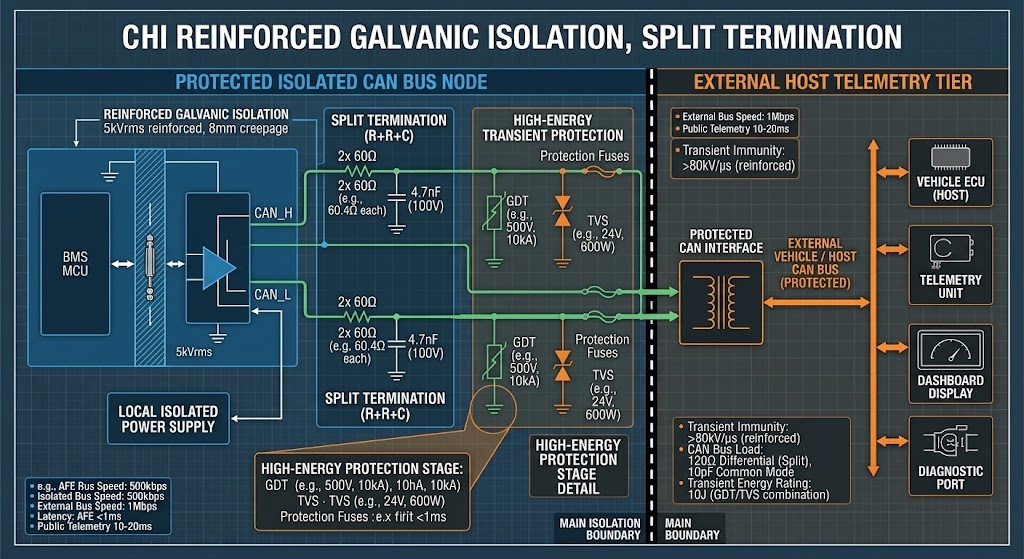
Split termination is mandatory to minimize radio-frequency emissions and maintain high common-mode signal rejection. Instead of a single 120Ω resistor placed across CAN_H and CAN_L at each physical bus endpoint, our BMS hardware utilizes two matched 60.4Ω ±1% metal film resistors connected in series, with the center tap decoupled directly to isolated ground through a 4.7nF, 100V ceramic capacitor.
Transient voltage suppression requires a dedicated array of bidirectional TVS diodes (such as Semtech SD05C or Littelfuse SM24CANB-02HTG) rated for > 30kV human-body contact electrostatic discharge (ESD) per IEC 61000-4-2, alongside a common-mode choke presenting > 51μH impedance at 10MHz to eliminate common-mode inverter ripple.
Data Link & Transport Protocol: 11-Bit vs 29-Bit Identifiers and CAN FD Payload Sizing
Arbitration framing dictates message delivery priority when multiple electronic control units (ECUs) broadcast simultaneously. The CAN specification defines two frame identifier variants: Standard 11-bit identifiers (CAN 2.0A) and Extended 29-bit identifiers (CAN 2.0B). High-voltage battery systems utilize the 29-bit architecture, typically conforming to the SAE J1939 Standard, which decomposes the identifier into Priority, Parameter Group Number (PGN), and Source Address (SA).
A primary bottleneck in complex packs is bus load saturation. The theoretical instantaneous bus utilization factor ($U$) on a Classical CAN network is derived through the sum of all transmitted message frames per second multiplied by total bits per frame, accounted for worst-case bit stuffing:
Bit_Total = 80 + 10 × Payload_Bytes + ⌊(34 + 8 × Payload_Bytes – 1) / 4⌋
Bus_Load (%) = (∑ [Bit_Totali × Frame_Ratei (Hz)] / Baud_Rate (bps)) × 100%
Where Bit_Total accounts for the 29-bit arbitration overhead, stuffing bits, CRC delimiter, and inter-frame spaces. If continuous bus load exceeds 40% on an industrial CAN bus, lower-priority frames experience non-deterministic arbitration latencies exceeding 250ms, triggering inverter comm-loss timeouts.
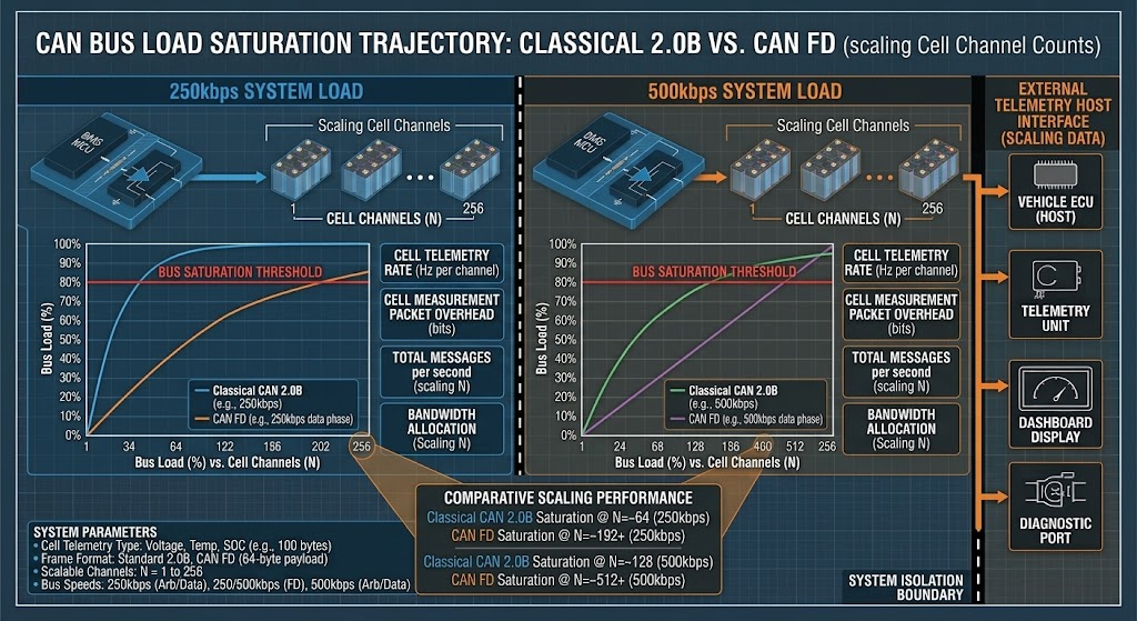
For systems exceeding 96 series cells (96S), Classical CAN 2.0B becomes saturated due to the 8-byte payload ceiling. Transmitting 96 cell voltages at 16-bit resolution requires 24 discrete frames every 100ms. Moving to CAN FD (Flexible Data-rate) expands the payload field to 64 bytes per frame and increases data-phase baud rates from 500kbps to 2Mbps or 5Mbps, reducing telemetry overhead by more than 80%.
High-Voltage Multi-Channel (96S-192S) Architecture Case Study: Solving Telemetry Saturation
Deploying high-density lithium storage into megawatt-scale commercial energy storage systems (BESS) or heavy industrial autonomous guided vehicles (AGVs) exposes acute data throughput limitations. In a recent engineering validation project conducted at JHY Battery reliability laboratories, a 192S 614.4V 280Ah LiFePO4 rack system experienced periodic bus dropouts when linked to a 250kW central power conversion system (PCS).
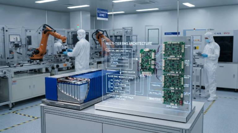
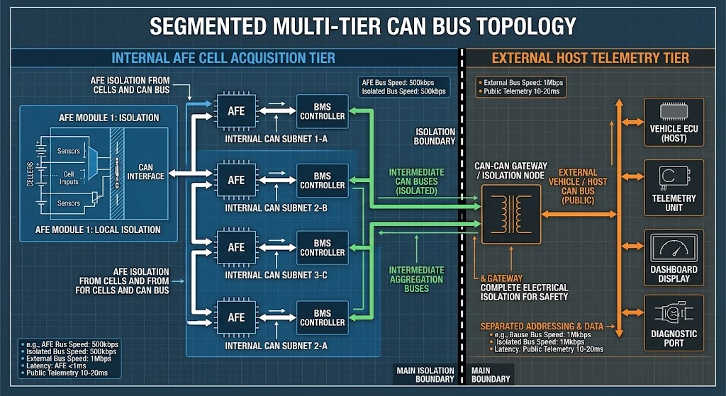
To eliminate this failure mode, JHY Battery embedded engineers segmented the network into a dual-bus architecture: an Internal Acquisition Bus (CAN-A) and an External Host Inverter Bus (CAN-B):
- CAN-A (Internal Isolated Bus): Runs a 500kbps proprietary deterministic protocol. Twelve 16-channel daisy-chained Analog Front End (AFE) modules (Texas Instruments BQ79616 or Analog Devices LTC6813) stream individual cell voltages and local temperatures directly to the Master BMS MCU at 20ms update cycles.
- CAN-B (External Industrial Bus): Interfaces with the host PCS/inverter via standard SAE J1939 or CANopen (CiA 418/454). The Master BMS processor aggregates cell telemetry, performs real-time Extended Kalman Filtering, and only broadcasts aggregate pack metrics, min/max/average cell delta registers, and dynamic charge limits at 100ms intervals, reducing external bus load to a stable 18.2%.
Telemetry Register Mapping: Byte-Level Engineering Definitions
To avoid integration ambiguity between mechanical battery pack assemblers and vehicle system programmers, all registers must be fully defined with scaling factors, offsets, value ranges, and byte endianness. JHY Battery utilizes Motorola (Big-Endian) byte ordering across all production DBC mappings to maintain strict industrial automation compatibility.
| Byte Pos | Signal Name | Data Type | Scale | Offset | Range | Unit |
|---|---|---|---|---|---|---|
| Byte 0-1 | Pack_Total_Voltage | uint16_t | 0.1 | 0 | 0.0 to 1,000.0 | V |
| Byte 2-3 | Pack_Current_Instantaneous | int16_t | 0.1 | -3,200.0 | -3,200.0 to +3,200.0 | A |
| Byte 4 | Pack_State_Of_Charge | uint8_t | 0.5 | 0 | 0.0 to 100.0 | % |
| Byte 5 | Pack_State_Of_Health | uint8_t | 0.5 | 0 | 0.0 to 100.0 | % |
| Byte 6 | Rolling_Alive_Counter | uint8_t (lower 4 bits) | 1 | 0 | 0 to 15 | counts |
| Byte 7 | Message_CRC8_Checksum | uint8_t | 1 | 0 | 0x00 to 0xFF | hex |
Addressing LiFePO4 Voltage Plateaus: Transmitting EKF SOC and SOH Confidence Flags
In industrial LiFePO4 battery systems, Open Circuit Voltage (OCV) profiling is inherently unviable across the 20% to 80% SOC operating envelope. The electrochemical voltage-to-SOC gradient (
dV/dSOC\mathrm{d}V/\mathrm{d}SOC) drops below 1.5mV per 1% SOC across this plateau.
Standard Coulomb counting experiences cumulative drift due to current shunt temperature offsets, analog-to-digital converter (ADC) non-linearities, and unmeasured parasite side-reactions. To solve this, JHY Battery BMS firmware incorporates an Extended Kalman Filter (EKF) combining a second-order Resistor-Capacitor (2-RC) Thevenin equivalent circuit model with continuous real-time impedance parameter estimation.
Our CAN protocol specification transmits an explicit EKF_SOC_Confidence_Grade byte alongside the raw calculated SOC. If the battery operates within the flat plateau without experiencing a rest-state OCV calibration (defined as current < 50mA continuous for ≥ 30 minutes) for over 10 charge-discharge cycles, the confidence metric drops. This alerts host control loops to schedule a top-of-charge synchronization above 3.45V/cell.
Closed-Loop Closed-System Control: Dynamic CCL/DCL and Inverter Handshake Protocols
Static battery protection thresholds that instantly snap contactors open under peak loads cause severe inductive voltage spikes (
V=−L⋅di/dtV = -L · \mathrm{d}i/\mathrm{d}t), damaging DC-bus link capacitors and inverter switches. High-reliability architectures enforce closed-loop dynamic control.
The BMS dynamically calculates and broadcasts the Maximum Continuous Charge Current Limit (CCL) and Continuous Discharge Current Limit (DCL) every 100ms on frame 0x18FF02F4. The host inverter must treat these values as rigid upper constraints for its current control loops. The BMS derates these values continuously based on four boundary conditions:
CCL = Min(IThermal_Max(Tcell), IOvervoltage_Derate(Vmax_cell), ISOC_Limit, IInternal_R)
During startup, the BMS executes a deterministic contactor closure state machine:
- State 1 (Standby): Main contactors open; BMS executes hardware self-test and checks insulation resistance via integrated ground-fault detection (> 500kΩ/V standard).
- State 2 (Pre-charge Actuation): Negative contactor closes, followed by the Pre-charge relay. Current is limited by a high-pulse ceramic resistor to charge inverter DC-link capacitors.
- State 3 (Delta-V Verification): Once inverter bus voltage reaches ≥ 95% of aggregate battery pack voltage within 500ms, the main positive contactor closes.
- State 4 (Normal Operation): Pre-charge relay opens after a 50ms overlap delay to prevent contactor pitting. Closed-loop CCL/DCL broadcasting commences.
Production DBC File Specification and C-Struct Code Implementations
To eliminate translation errors between battery hardware specifications and host software deployment, JHY Battery provides verified Vector CANdb++ (.dbc) configuration databases with every custom pack delivery. Below is a syntactically compliant DBC definition covering aggregate pack telemetry and dynamic charge limits:
VERSION "JHY_BMS_CAN_V2.6_2026"

NS_ :
BS_ :

BU_ : BMS INVERTER

BO_ 2566840052 BMS_Status_Frame: 8 BMS
 SG_ Pack_Voltage : 7|16@0+ (0.1,0) [0|1000] "V" INVERTER
 SG_ Pack_Current : 23|16@0- (0.1,0) [-3200|3200] "A" INVERTER
 SG_ Pack_SOC : 39|8@0+ (0.5,0) [0|100] "%" INVERTER
 SG_ Pack_SOH : 47|8@0+ (0.5,0) [0|100] "%" INVERTER
 SG_ Alive_Counter : 51|4@0+ (1,0) [0|15] "counts" INVERTER
 SG_ CRC8_Checksum : 63|8@0+ (1,0) [0|255] "hex" INVERTER

BO_ 2566840308 BMS_Dynamic_Limits: 8 BMS
 SG_ Max_Charge_Current_Limit : 7|16@0+ (0.1,0) [0|1500] "A" INVERTER
 SG_ Max_Discharge_Current_Limit : 23|16@0+ (0.1,0) [0|2000] "A" INVERTER
 SG_ Charge_Cutoff_Voltage : 39|16@0+ (0.1,0) [0|1000] "V" INVERTER
 SG_ Discharge_Cutoff_Voltage : 55|16@0+ (0.1,0) [0|1000] "V" INVERTER
The corresponding production-grade ANSI-C firmware parser for embedded integration is structured as follows, featuring deterministic bit-shifting and an integrated SAE J1850 CRC-8 calculation:
#include <stdint.h>
#include <stdbool.h>

typedef struct {
    float pack_voltage_v;
    float pack_current_a;
    float state_of_charge_pct;
    float state_of_health_pct;
    uint8_t alive_counter;
    uint8_t crc8_checksum;
} JHY_BMS_Status_t;

/ SAE J1850 CRC-8 calculation polynomial: X^8 + X^4 + X^3 + X^2 + 1 (0x1D) /
uint8_t Calculate_CRC8(const uint8_t *data, uint8_t length) {
    uint8_t crc = 0xFF;
    for (uint8_t i = 0; i < length; i++) {
        crc ^= data[i];
        for (uint8_t bit = 0; bit < 8; bit++) {
            if (crc & 0x80) {
                crc = (crc << 1) ^ 0x1D;
            } else {
                crc <<= 1;
            }
        }
    }
    return crc ^ 0xFF;
}

bool Parse_BMS_Status_Frame(const uint8_t rx_bytes[8], JHY_BMS_Status_t *out_telemetry) {
    / Validate message integrity /
    uint8_t calculated_crc = Calculate_CRC8(rx_bytes, 7);
    if (calculated_crc != rx_bytes[7]) {
        return false; / CRC failure, drop frame /
    }

    / Unpack Motorola (Big-Endian) byte sequences /
    uint16_t raw_voltage = ((uint16_t)rx_bytes[0] << 8) | rx_bytes[1];
    int16_t  raw_current = ((int16_t)rx_bytes[2] << 8)  | rx_bytes[3];
    uint8_t  raw_soc     = rx_bytes[4];
    uint8_t  raw_soh     = rx_bytes[5];
    uint8_t  raw_counter = rx_bytes[6] & 0x0F;

    / Apply calibration scaling factors /
    out_telemetry->pack_voltage_v        = (float)raw_voltage * 0.1f;
    out_telemetry->pack_current_a        = (float)raw_current * 0.1f;
    out_telemetry->state_of_charge_pct   = (float)raw_soc * 0.5f;
    out_telemetry->state_of_health_pct   = (float)raw_soh * 0.5f;
    out_telemetry->alive_counter         = raw_counter;
    out_telemetry->crc8_checksum         = rx_bytes[7];

    return true;
}
DFM Engineering Watch-Outs: Boundary Conditions, Real-World Pitfalls, and Validation
Design for Manufacturing (DFM) issues often emerge during harsh environmental exposure and long-term storage rather than initial prototype testing on the bench. Engineering specifications must resolve these edge cases during the initial RFQ.
1. Sub-Zero Charging & Boundary Temperature Windows: A flat temperature specification (e.g. “-40°C to +60°C”) is unacceptable. While advanced cells utilizing nano-coated electrodes and low-viscosity electrolytes can safely discharge down to -40°C (retaining ≥ 55% rated capacity at 0.2C rate, and ≥ 75% at -20°C), charging below 0°C is strictly prohibited. Forcing charge current into standard graphite anodes below 0°C induces metallic lithium plating, resulting in permanent dendrites, capacity fading, and catastrophic internal short circuits. JHY Battery designs incorporate integrated silicone heating mats managed directly by the BMS: when low temperatures are detected, charge current is routed exclusively to internal heating elements until cell temperatures reach +5°C, at which point charging commences safely.
2. Cell Sorting Tolerances: Multi-cell pack stability depends on raw electrochemistry balance before BMS balancing is introduced. JHY Battery guarantees a 0.03% (300 PPM) pack defect rate through 100% automated MES cell screening: open-circuit voltage matching (
ΔV≤3mVΔ V ≤ 3mV), 1kHz AC internal resistance matching (
ΔACIR≤0.3mΩΔ ACIR ≤ 0.3mΩ), absolute discharge capacity matching (
ΔC≤1.0%Δ C ≤ 1.0\%), and static self-discharge tracking ($K$-value evaluation over a mandatory 14 to 28-day aging isolation period).
3. Analog Front End (AFE) Sensing Accuracy: The BMS hardware must utilize automotive-grade AFEs (such as the TI BQ-series or ADI LTC-series) providing individual cell voltage measurement precision within ±1.5mV across the complete automotive temperature profile (-40°C to +105°C). Lower-tier ICs with ±10mV or higher deviations cannot detect single-cell overcharging in LiFePO4 cells approaching the steep 3.65V end-of-charge curve.
4. Quiescent Sleep Drain and Tab Fatigue: Prolonged logistics transit and warehouse storage can lead to pack bricking if BMS sleep current draws exceed limits. JHY Battery BMS firmware features a tiered low-power hierarchy: Active Run (< 25mA), Standby (< 2mA), and Deep Sleep Ship Mode (< 15μA). Additionally, our packs utilize flexible nickel-copper composite busbars and strain-relief wiring channels to prevent mechanical vibration (tested to IEC 60068-2-64 standards) from inducing fatigue fractures on CAN communication and voltage sense tabs.
All safety-critical systems are backed by full battery compliance certifications and testing, including UN38.3 transport safety, UL 1973, UL 9540A, IEC 62619, and ISO 13485 medical device quality management systems.
Frequently Asked Questions (FAQ) on BMS CAN Protocol Integration
Why deploy CAN FD over Classical CAN 2.0B in 96S+ high-voltage battery packs?
Classical CAN 2.0B caps payloads at 8 bytes. For a 96S system, transmitting individual cell voltages with 16-bit resolution requires 24 distinct frames. At 250kbps and 100ms broadcast cycles, this single stream consumes over 35% of the total bus capacity, inducing latency spikes and message drops. CAN FD increases the data payload to 64 bytes per frame, aggregating all 96 cell voltages into just 3 frames while switching to a 2Mbps or 5Mbps data-phase bitrate, reducing total bus utilization to under 6%.
How does JHY Battery prevent LFP SOC drift over the flat 3.2V to 3.3V open-circuit plateau?
JHY Battery BMS firmware avoids static OCV-SOC mapping across the 20% to 80% SOC region where dV/dSOC is under 1.5mV/%. Instead, we execute an Extended Kalman Filter (EKF) combining high-precision Coulomb counting (0.1mA resolution shunt sensing) with an adaptive electrochemical cell equivalent circuit model (Thevenin ECM). The BMS transmits both SOC and an EKF Covariance/Confidence byte via CAN, automatically recalibrating to OCV only when resting conditions (current < 50mA for ≥ 30 minutes) are verified.
How can hardware engineers audit and verify BMS CAN bus physical layer integrity?
Audit physical integrity using a differential oscilloscope: measure CAN_H and CAN_L with respect to isolated logic ground. Recessive state must measure 2.5V ±0.2V on both lines with differential voltage Vdiff = 0V. Dominant state must yield CAN_H at 3.5V and CAN_L at 1.5V (Vdiff = 2.0V ±0.5V). Verify split termination resistance equals 60 ohms across CAN_H and CAN_L with the pack unpowered. Ensure transceiver galvanic isolation is tested to 2.5kV RMS per UL 1577 with CMTI exceeding 100kV/µs.
What documentation and software assets should be required in a BMS CAN RFQ?
A complete B2B RFQ must mandate: (1) Vector CANdb++ syntactically compliant .DBC file, (2) Frame Arbitration Matrix specifying 11-bit standard vs 29-bit extended IDs, cycle rates, and endianness (Motorola/Big-Endian standard), (3) Full dynamic charge/discharge current limit (CCL/DCL) control algorithm documentation, (4) Pre-charge and main contactor sequencing state machine chart, and (5) Unified Diagnostic Services (UDS / ISO 14229) FOTA specification over CAN.
Turnkey Custom Pack Prototyping: 3-Step Integration & Sizing Action Plan
Translating an RFQ specification into a verified, field-ready battery pack requires tight coordination between electrochemistry, mechanical enclosures, and embedded systems engineering. JHY Battery (China Battery Manufacturer) brings over 30 years of industrial battery pack manufacturing, supported by 1,200+ employees and 800+ R&D and electrical engineers.
The 3-Step Custom Engineering Funnel
- Step 1: System Sizing & Specification: Define cell chemistry (NMC, LiFePO4, LTO), cell form factor (prismatic, 21700, pouch), series/parallel configurations, physical envelope, peak current profiles, and host communication layer (CAN 2.0B, CAN FD, J1939, CANopen).
- Step 2: DFM Review & Digital Twin Simulation: JHY Battery BMS engineers analyze communication payloads, calculate bus loading ceilings, generate custom DBC mapping files, and validate EMC physical layer schematics within 48 hours.
- Step 3: Rapid Prototyping & HIL Validation: Receive functional, custom-engineered lithium battery prototypes complete with factory Hardware-in-the-Loop (HIL) Vector CANoe test reports within 5 to 7 business days.
Direct Engineering Contacts: Simple@chinabatterymanufacturer.com | joeshen@chinabatterymanufacturer.com | WhatsApp/Phone: +86-18575997879