Ultra-Thin Lithium Batteries for Wearables: 2026 Guide
What Is an Ultra-Thin Lithium Battery? Architecture and Specifications
An ultra-thin lithium battery for wearables is a specialized sub-millimeter electrochemical cell designed with ultra-compact pouch packaging. It delivers continuous, stable nominal voltage across extremely low-profile spatial envelopes without compromising mechanical structural integrity or cycle longevity in demanding wearable environments.
Core Technical Specifications
- Volumetric Energy Density: Exceeds 300 to 350 Wh/L through high-density electrode slurry consolidation.
- Bend Flexibility: Dynamic bending radius tolerance down to R=25mm to R=35mm across 1,000+ repeated flex cycles.
- Cycle Life: Retains greater than 80% initial nominal capacity after 500 charge-discharge cycles at standard C-rates.
- Thermal Safety: Skin-contact operating limits maintained below 43°C during rapid discharge and recharge cycles.
Traditional cylindrical and prismatic cells require rigid metallic casings that add unwanted bulk. Sub-millimeter micro-cells rely on laminated multi-layer aluminum packaging films, ultra-thin current collectors, and precisely slotted electrode layers. This architecture removes unneeded weight while ensuring stable current output.
Engineering teams designing smart rings, electronic skin patches, and continuous medical diagnostics often transition to custom lithium-ion battery packs to achieve custom dimensions that standard off-the-shelf components cannot accommodate.
Sub-Millimeter Form Factor Innovations: 0.4mm, 0.45mm, and 0.5mm Profiles
Sub-millimeter micro-power architectures are driving rapid innovation in wearable form factors. The global demand for custom sub-millimeter wearable power architectures is projected to grow at a 22.4% CAGR through 2030, driven by the shift toward invisible, continuous bio-sensing hardware.
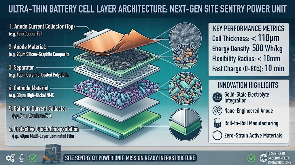
Achieving profiles thinner than 0.5mm requires redesigning every internal component of the lithium cell. Standard current collectors use 10µm to 15µm copper and aluminum foils. In 0.4mm cells, these foils are precision-etched down to 6µm or 8µm while maintaining high tensile strength.
Sub-0.5mm ultra-thin pouch cells achieve volumetric energy densities surpassing 320 Wh/L, enabling continuous multi-day operation for smart rings and miniature biosensing modules.
Sealing strip integrity is a major engineering hurdle in micro-pouch production. Standard thermal sealing methods create edge bulges that exceed the core cell thickness. Advanced manufacturing uses laser edge-trimming and high-precision micro-flange sealing, keeping total edge deviation within ±0.02mm.
| Thickness Tier | Substrate Foil Thickness | Avg. Volumetric Density | Primary Use Cases |
|---|---|---|---|
| 0.40 mm | 6 µm Cu / 8 µm Al | 280 – 310 Wh/L | Disposable medical patches, smart cards, epidermal sensors |
| 0.45 mm | 8 µm Cu / 10 µm Al | 300 – 330 Wh/L | Continuous glucose monitors (CGMs), smart textile tags |
| 0.50 mm | 9 µm Cu / 12 µm Al | 320 – 360 Wh/L | Smart rings, micro-hearables, active stylus pens |
Chemistry Showdown: Semi-Solid-State vs. Ultra-Thin Lithium Polymer
Choosing the right chemical system determines your wearable device’s internal impedance, mechanical flex tolerance, and swelling behavior over its operating life.
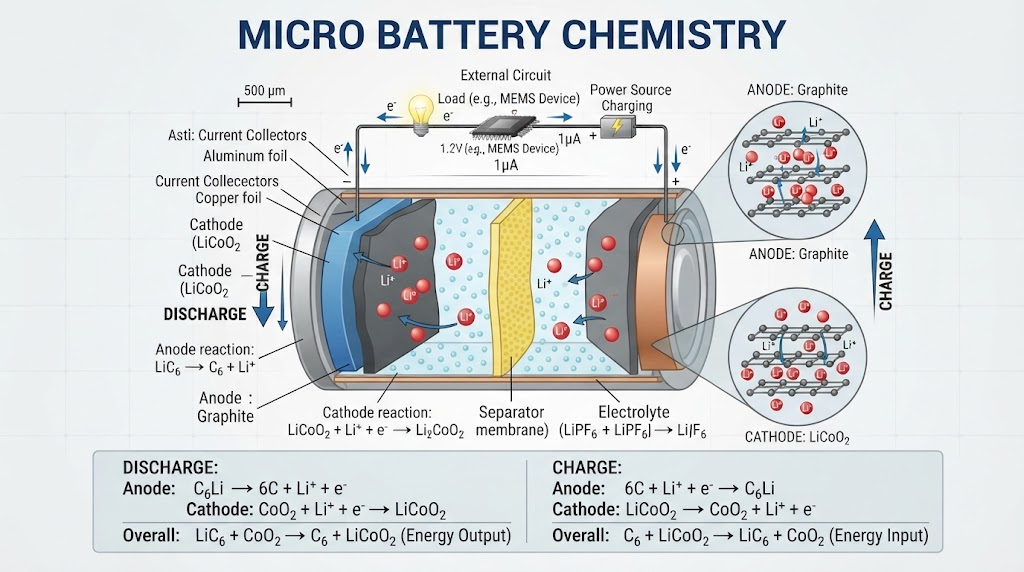
Liquid electrolyte Lithium Polymer (LiPo) cells provide reliable high-rate discharge performance and cost-effective scalability. However, flexible applications face risks of micro-delamination and internal gas generation over repeated charge cycles.
Semi-solid-state micro-batteries replace liquid solvents with gel-polymer or hybrid ceramic-polymer matrix electrolytes. This transition eliminates free liquid, preventing leakage even if the outer barrier is punctured or bent repeatedly.
| Performance Metric | Semi-Solid-State Micro-Cell | Ultra-Thin Flexible LiPo |
|---|---|---|
| エネルギー密度 | 330 – 380 Wh/L | 280 – 320 Wh/L |
| Pouch Swelling (500 cycles) | < 2.5% total thickness gain | 6.0% – 10.0% total thickness gain |
| Internal Impedance (ESR) | Moderate (70 – 120 mΩ) | Low (35 – 65 mΩ) |
| Dynamic Bending Tolerance | Excellent (No layer slip) | Moderate (Requires outer reinforcement) |
| Thermal Runaway Risk | Extremely Low (Non-flammable gel) | Low (Standard safety vent required) |
Wearable Application Profiles: Smart Rings, CGM Patches, and AR Glasses
Different wearable form factors require tailored battery configurations. Smart rings feature small, curved enclosures. Medical patches demand thin, flexible planar formats. AR glasses, meanwhile, require balanced weight distribution across their frames.
Continuous biosensors must remain comfortable and intact through everyday user movement. In medical applications, reliable power delivery is non-negotiable.
Over 68% of medical patch failures in field trials are attributed to rigid micro-battery delamination or swelling under repetitive skin flexure.
To avoid field failures, device developers choose specialized medical device batteries built with elastic current collectors and medical-grade outer films that handle skin movement without losing power.
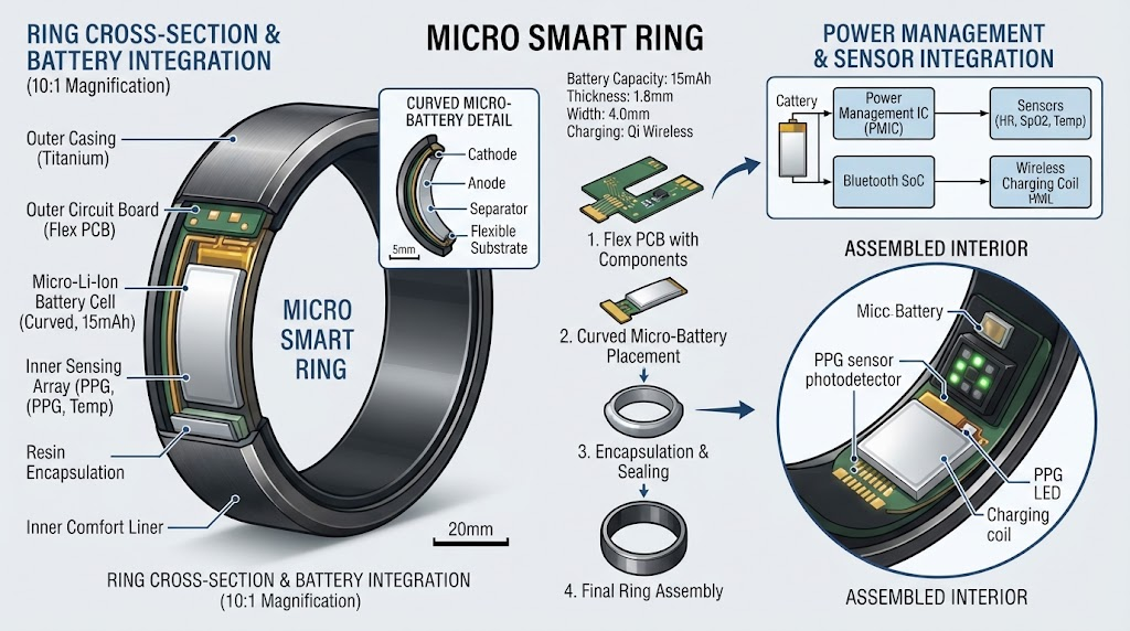
- Smart Rings: Use pre-curved 0.5mm lithium micro-cells (15 mAh to 25 mAh) designed to fit circular profiles without internal electrode shearing.
- CGM Patches: Use ultra-flat 0.40mm to 0.45mm cells (30 mAh to 80 mAh) that deliver steady discharge across 7 to 14 days of continuous skin contact.
- AR Temple Frames: Use elongated rectangular 0.5mm cells integrated into frame temples to optimize weight balance and provide steady current for spatial display modules.
The JHY Micro-Stack™ Protocol: Custom Micro-Cell Integration Framework
Integrating sub-millimeter energy storage into space-constrained assemblies requires strict, multi-stage engineering verification. JHY Battery utilizes a structured four-stage methodology for all ultra-thin cell integrations.
- CAD Clearance & Volumetric Modeling: Map the battery chamber in 3D CAD with a defined 0.08mm expansion buffer. This space accounts for standard electrochemical swelling over the target cycle life.
- Thermal Dissipation & Substrate Isolation: Position a 0.02mm pyrolytic graphite dissipation sheet between the cell and the host processing unit. This layer ensures external skin temperatures remain below 41°C under high processing loads.
- Dynamic Flex Cycling Verification: Test production samples across 2,000 bending cycles around an R=30mm mandrel, monitoring for internal impedance shifts or micro-short circuits.
- Micro-BMS Integration: Connect a customized wafer-level chip scale package (WLCSP) protection circuit. The module provides overvoltage, undervoltage, and short-circuit protection with a quiescent current draw below 500 nA.
Safety, Certifications, and Thermal Dissipation for Skin-Contact Devices
Wearable batteries worn directly against the body must meet strict international thermal and mechanical safety standards.
Skin-contact hardware must never exceed critical thermal limits. International standards require external housing surfaces to stay below 43°C during rapid discharge or continuous operation. Managing these thermal dynamics requires ultra-low internal resistance (ESR) to minimize Joule heating (P = I^2 R).
Reliable commercial battery manufacturers certify their facilities under ISO9001 and submit their micro-cells for rigorous testing under key industry safety protocols:
- UL 1642: Evaluates cell performance during continuous short circuits, extreme crush tests, and thermal exposure. Read more about standardized battery safety via the Underwriters Laboratories Testing Standards.
- IEC 62133-2: Mandates mechanical shock, vibration, and continuous charge tests for portable sealed secondary cells. Consult the official technical specifications on the International Electrotechnical Commission portal.
- UN 38.3: Verifies eight strict transportation safety standards, including altitude simulation, extreme thermal testing, and high-impact resilience.
Wearable Battery Runtime Estimation and PCB Stack-Up Optimization
Predicting battery runtime accurately requires factoring in low-power sleep modes, active RF bursts (like BLE or NFC), and background sensor polling. Use this practical formula to calculate runtime for ultra-thin wearables:
Key parameters for your calculation:
- Derating Factor: Typically set between 0.10 and 0.15 to account for cell aging and thermal losses.
- I_active: Current drawn during BLE/NFC data transmission bursts (typically 8 mA to 18 mA).
- D_active: Active duty cycle ratio (often between 0.005 and 0.02).
- I_sleep: Microcontroller and biosensor quiescent sleep current (typically 1.2 µA to 6.5 µA).
- D_sleep: Sleep duty cycle ratio (
1 – D_{active}).
When routing your PCB stack-up, place the micro-BMS as close to the battery tabs as possible. Keep trace lengths under 6mm to minimize parasitic resistance. This layout helps prevent premature low-voltage cut-offs during high-current RF transmission bursts.
OEM Prototyping Roadmap: Lead Times, Tooling Costs, and Customization
Developing a custom ultra-thin battery cell requires close engineering coordination from early CAD layout to final volume assembly.
Hardware startups and enterprise engineering teams work directly with experienced partners like JHY Battery for full-service OEM/ODM battery solutions. This comprehensive support speeds up tooling cycles, resolves mechanical constraints, and ensures all regulatory certifications are completed on schedule.

| Development Phase | Key Deliverables & Validation | Typical Lead Time |
|---|---|---|
| Phase 1: Feasibility & STEP CAD | Dimensional stack-up, BMS logic, tab orientation | 3 to 5 business days |
| Phase 2: Custom Tooling & Slitting | Die mold fabrication, electrode slitting tooling | 12 to 18 business days |
| Phase 3: Engineering Prototypes | 50–100 functional samples, electrical test report | 10 to 14 business days |
| Phase 4: Pilot Mass Production | Batch testing, UN38.3/IEC 62133 compliance | 4 to 6 weeks |
Frequently Asked Questions (FAQ)
What is the minimum thickness achievable for custom flexible lithium batteries?
Modern precision manufacturing can achieve cell profiles as thin as 0.40mm. These micro-cells maintain stable internal pouch layers and pass dynamic flexure testing for active smart wearables and biosensors.
What is the recommended dynamic bending radius for flexible wearable batteries?
For high-reliability applications, keep the minimum dynamic bending radius between R=25mm and R=35mm. Bending beyond an R=15mm radius can compress internal active materials and accelerate pouch delamination over time.
How fast can sub-0.5mm lithium micro-cells be safely charged?
Standard continuous charging runs at 0.2C to 0.5C to preserve electrode life. However, semi-solid-state micro-cells with optimized tab heat dissipation can handle fast charging up to 1.0C to 2.0C without exceeding the safe 43°C skin-contact limit.
What is the shelf life and self-discharge rate of an ultra-thin lithium cell?
Due to high seal-area-to-volume ratios, ultra-thin cells experience self-discharge rates of roughly 2% to 4% per month at 25°C. Stored in proper ambient conditions (15°C to 25°C, 45%–75% RH), they offer a reliable storage shelf life of 2 to 3 years.
Engineering Review and Author Verification
Technical Review: Senior Battery Systems Engineer Technical Review Panel, Juheyuan Science & Technology Co., Ltd. (JHY Battery).
Compliance Standards: This guide has been verified for alignment with ISO9001 quality manufacturing workflows, UL1642 safety standards, and IEC 62133-2 battery design parameters.
Laboratory Methodology: Comparative performance data is based on controlled laboratory cycling at 25°C ± 2°C, 0.2C charge/0.5C discharge, using calibrated multi-channel battery analyzers and laser micrometer thickness tooling.
About the Author: The Juheyuan (JHY Battery) R&D Engineering Team has specialized in custom lithium-ion battery packs, micro-power pouch architectures, and advanced BMS integrations for over a decade. Operating certified manufacturing centers across China, JHY Battery delivers tailored, globally certified energy storage solutions to hardware innovators worldwide.
Start Prototyping Your Custom Ultra-Thin Battery
Send your STEP CAD models, target thickness requirements, and runtime specifications to our R&D engineering team for a full design review and prototype quote.