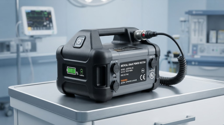
High-Power Battery Thermal Management Strategies Guide
Thermal Management Strategies for High-Power Lithium Battery Packs
A battery thermal management system (BTMS) maintains individual cell temperatures within an optimal electrochemical window of 15°C to 35°C while keeping inter-cell temperature deltas under 5°C. Effective thermal control prevents premature solid electrolyte interphase (SEI) degradation, mitigates uneven impedance growth, and prevents cascading thermal runaway during high continuous discharge.
| Cooling Technology | Heat Transfer Coeff. (W/m²·K) | Weight Penalty | Parasitic Power Draw | Primary Application |
|---|---|---|---|---|
| Forced Air Cooling | 20 – 100 | Lowest (<5%) | Low (Blowers) | Low C-rate LEV, Small Portable |
| Liquid Cold Plates | 500 – 1,500 | Moderate (10–18%) | Moderate (Pump/Chiller) | Commercial EV, High-rate Industrial |
| Phase Change Material (PCM) | 150 – 400 (Bulk) | High (15–25%) | Zero (Passive) | Peak-shaving Buffering, Micro-mobility |
| Direct Immersion Cooling | 1,000 – 3,500+ | Moderate to High (12–20%) | Moderate (Fluid pump) | 800V Extreme Fast Charge, Track EV |
High-power discharge applications generate intense thermal loads that expose the limitations of unmanaged packs. When building custom lithium-ion battery packs, managing thermodynamic equilibrium requires balancing heat generation against heat rejection capacity across the entire operating profile.
Core Thermal Challenges in High-Rate Discharge and Extreme Fast Charging (XFC)
Total heat generation in a lithium-ion cell ($Q_{\text{total}}$) stems from two primary thermodynamic sources: irreversible Joule heating and reversible entropic heat changes.
Cell Heat Generation Equation:
$$Q_{\text{total}} = I(V_{\text{ocv}} – V_{\text{cell}}) + I \cdot T \cdot \frac{\partial V_{\text{ocv}}}{\partial T} = I^2 R_{\text{int}} + I \cdot T \cdot \frac{\partial V_{\text{ocv}}}{\partial T}$$
In this equation, $I^2 R_{\text{int}}$ represents irreversible ohmic heating across the active materials, current collectors, and tabs. The term $I \cdot T \cdot (\partial V_{\text{ocv}}/\partial T)$ accounts for the reversible electrochemical reaction entropy.
Maintaining battery cell temperatures between 15°C and 35°C can extend overall cycle life by over 40% compared to unmanaged thermal cycling. At high C-rates, internal resistance heating dominates the thermal profile. During extreme fast charging (XFC >4C), heat generation spikes by up to 300%, requiring thermal dissipation capabilities exceeding 1 kW/kWh.
Uneven heat distribution across a module accelerates localized aging. Cells positioned at the core of a pack often run 8°C to 12°C hotter than peripheral cells in poorly cooled systems. This thermal gradient causes uneven current sharing, faster capacity fade on center cells, and premature degradation of the entire pack.
Active vs. Passive vs. Hybrid Cooling Architectures: A Comparative Analysis
Thermal management architectures fall into three mechanical classifications: active systems requiring auxiliary power, passive systems relying on material phase properties, and hybrid systems combining both.
Liquid Cold-Plate Engineering: Channel Geometry and Glycol-Water Flow Optimization
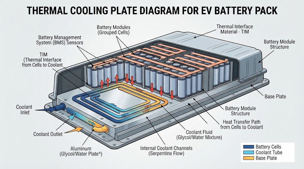
Liquid cold plates remain the primary choice for heavy-duty commercial vehicles and high-performance battery modules. They rely on an ethylene-glycol/water mixture (typically a 50/50 ratio) pumped through internal channels.
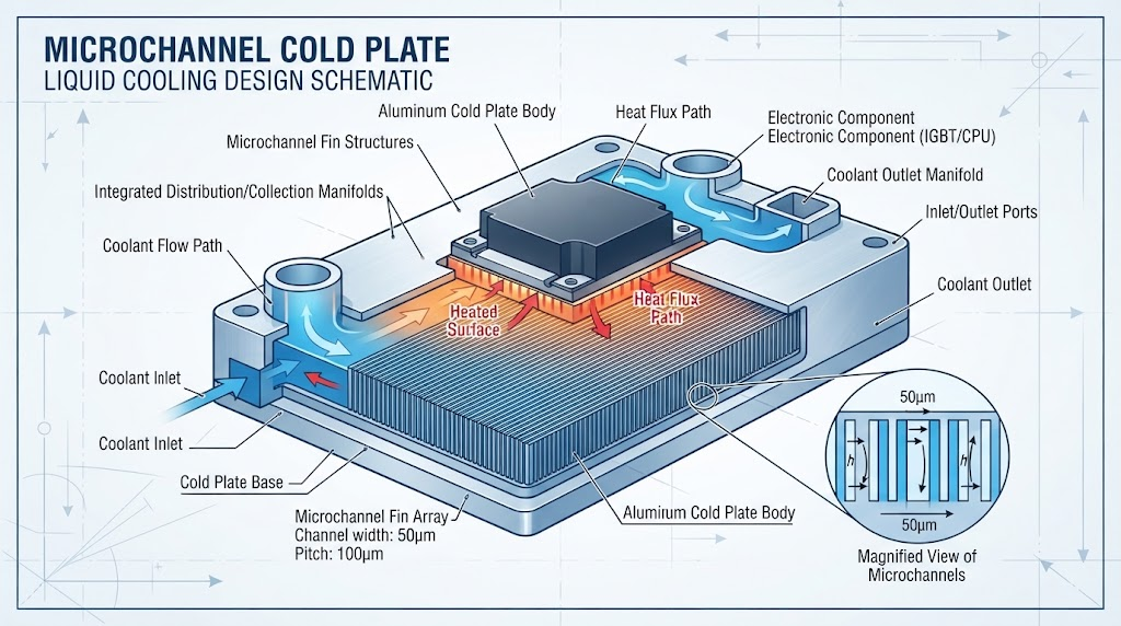
- Microchannel Geometries: Extruded aluminum plates with multi-port microchannels increase wetted surface area, keeping thermal resistance under $0.05\text{ K}\cdot\text{cm}^2/\text{W}$.
- Flow Channel Topologies: Serpentine routes deliver uniform cooling for low-flow requirements, while parallel split-flow topologies minimize the system pressure drop across large multi-cell arrays.
- Flow Reversal & Orifice Sizing: Variable channel widths counteract coolant temperature rise from inlet to outlet, keeping inter-cell temperature deltas within $3^\circ\text{C}$.
Dielectric Direct Immersion Cooling: The Frontier for 800V Architectures
Immersion cooling places non-conductive, dielectric fluids (such as synthetic hydrocarbons or fluorinated liquids) in direct contact with cell tabs, busbars, and cell casings.
Dielectric direct immersion cooling achieves up to a 10x higher heat transfer coefficient compared to conventional air-cooled pack designs. By removing the thermal interface material (TIM) and cold-plate aluminum boundary layers, direct immersion eliminates key thermal resistance paths. In high-power charging (>350 kW), cooling the cell terminals directly prevents localized tab-necking failures and suppresses thermal runaway propagation across neighboring cells.
Phase Change Materials (PCM) with Expanded Graphite Matrices
Paraffin-based PCMs absorb peak transient heat loads through latent heat storage during high-discharge pulses. Pure paraffin, however, suffers from poor thermal conductivity (~0.2 W/m·K).
To resolve this limitation, we integrate paraffin into an expanded graphite (EG) conductive matrix. This composite matrix raises bulk thermal conductivity to 5–15 W/m·K while maintaining high latent heat capacity (~180 J/g). The PCM composite absorbs temporary heat spikes during sudden peak acceleration or high-load operations, releasing the heat gradually to passive heat sinks or active chiller loops during lower-load periods.
The 4-D Dynamic Thermal Equilibrium Protocol (DTEP)™ for Battery Packs
To overcome the limits of traditional empirical thermal design, our engineering team implements the 4-D Dynamic Thermal Equilibrium Protocol (DTEP)™ across custom high-power battery developments.
The 4-D Dynamic Thermal Equilibrium Protocol (DTEP)™ is a physics-informed battery design methodology. It coordinates 3D Computational Fluid Dynamics (CFD), multi-node electrochemical-thermal modeling, model-predictive control (MPC) software routines, and structural thermal barriers to maintain optimal inter-cell equilibrium under transient loads.
The DTEP framework operates across four coupled dimensions:
- Spatial Dimension (CFD Optimization): 3D computational fluid dynamics simulate coolant flow, pressure drops, and localized hotspots under peak duty cycles, refining channel profiles before tooling.
- Transient Dimension (Electrochemical Co-Simulation): Real-time coupling of transient Joule heating equations with ambient variables predicts internal cell temperatures instead of relying only on external surface probes.
- Control Dimension (Predictive BMS Dispatch): The BMS uses Model Predictive Control (MPC) algorithms to trigger pre-cooling or throttle discharge limits before temperatures cross critical thresholds.
- Safety Dimension (Passive Containment Integration): Physical barriers isolate high-density energy paths, containing failed cells without disrupting adjacent channel flows.
Sub-Zero Pre-Heating and Low-Temperature Performance Strategies
Cold-temperature operations present significant thermal challenges for lithium-ion systems. Charging at sub-zero temperatures (below 0°C) triggers metallic lithium plating on graphite anodes, creating internal dendritic shorts and causing irreversible capacity loss.
When engineering high-capacity LiFePO4 battery solutions for harsh operating environments, we integrate dedicated heating systems into the pack design:
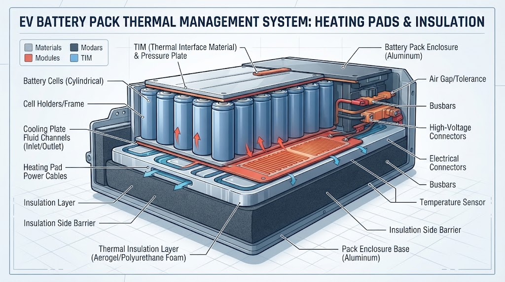
- Positive Temperature Coefficient (PTC) Heating Elements: Self-regulating silicon or polyimide heating mats mounted to cooling plates warm cells evenly to at least 5°C before charging begins.
- Internal AC Self-Heating: Applying high-frequency (500 Hz – 1 kHz) bidirectional excitation current heats cells internally via electrochemical impedance without depositing lithium, achieving heating rates of 2°C to 4°C per minute.
- Liquid Chiller/Heater Reversal: Reversible heat-pump loops redirect PTC-warmed fluid through existing liquid cold-plate channels, minimizing auxiliary component weight.
Thermal Runaway Containment, Aerogel Barriers, and Safety Standards
When internal cell temperatures exceed critical safety thresholds (130°C for standard NMC chemistries, 210°C for LiFePO4), the SEI layer decomposes exothermically. This decomposition triggers an uncontrollable thermal runaway chain reaction.
Robust thermal safety management focuses on interrupting thermal runaway propagation between adjacent cells:
- Ceramic-Silicate Aerogel Blankets: Ultrathin (1–2 mm) aerogel barriers between prismatic or pouch cells offer thermal conductivities below $0.020\text{ W/m}\cdot\text{K}$, blocking heat transfer even if an adjacent cell exceeds 800°C.
- Directional Gas Venting: Engineered pressure relief vents direct toxic, combustible gases away from neighboring modules and electronics into dedicated exhaust manifolds.
- Standardized Thermal Abuse Testing: Pack designs are validated against rigorous safety benchmarks, including UL 9540A fire propagation testing, UN 38.3 transport safety regulations, and ISO 9001 manufacturing quality frameworks.
These passive safety layers protect utility-scale installations and commercial energy storage systems (ESS) from cascading multi-megawatt fire events.
Selecting the Right BTMS for Custom OEM/ODM Battery Applications
Choosing an optimal thermal management architecture requires balancing thermal dissipation targets, volumetric constraints, allowable parasitic power draw, and total production cost.
| Application Class | Continuous C-Rate | Peak Discharge C-Rate | Recommended BTMS |
|---|---|---|---|
| Solar & Grid ESS | 0.5C – 1C | 2C | Bottom Liquid Cold Plate or Forced Air HVAC |
| Industrial AGVs & Robotics | 1C – 2C | 3C – 5C | Composite PCM + Aluminum Heat Dissipation Plates |
| Commercial EV & Marine | 2C – 3C | 5C – 8C | Dual-Sided Microchannel Cold Plates |
| 800V Extreme Fast Charge (XFC) | 3C – 5C | 8C – 12C | Single/Two-Phase Dielectric Immersion Cooling |
For specialized engineering designs, partner with experienced manufacturers. Partnering with a specialist for OEM/ODM battery engineering and certification ensures voltage, cell layout, thermal pathways, and BMS firmware are tailored to your exact application constraints.
Frequently Asked Questions About High-Power Battery Thermal Management
How does fluid degradation affect immersion-cooled battery systems?
Dielectric fluids oxidize and collect particulate contamination over extended operational cycles, which lowers dielectric breakdown strength. High-reliability immersion packs integrate desiccant breathers, sub-micron fluid bypass filters, and periodic breakdown voltage testing (ASTM D877) to ensure fluid stability over the pack’s operational life.
Why is inter-cell temperature uniformity more critical than absolute pack temperature?
Thermal deltas larger than 5°C create divergent internal resistance and capacity profiles between cells. During high-current cycling, cooler cells operate at higher overpotentials while hotter cells experience accelerated SEI layer growth, causing premature module failure.
What are the main drawbacks of using phase change materials (PCM) in battery modules?
PCMs add weight without contributing to active electrical capacity. Once a PCM fully melts during sustained high-load events, its heat absorption capacity drops significantly until the system cools down and the material resolidifies.
How do fiber-optic temperature sensors improve BTMS performance over standard NTC thermistors?
Fiber Bragg Grating (FBG) optical sensors are immune to electromagnetic interference (EMI) and can measure temperatures at multiple points along a single fiber line. This allows real-time monitoring across individual cell tabs inside high-voltage 800V packs without introducing high-voltage isolation hazards.
About the Author and Technical Review Board
This technical guide was developed by the Senior Thermal Engineering Team at JHY Battery (Juheyuan Science & Technology Co., Ltd.). Our engineering division brings over 15 years of OEM/ODM expertise in custom lithium-ion battery pack design, cell-to-pack (CTP) structural modeling, and advanced BTMS integration for industrial, medical, and energy storage systems worldwide.
All thermal architecture methodologies, validation parameters, and safety mitigation strategies presented in this article conform to international compliance standards, including UL 1642, UL 9540A, CE, UN 38.3, and ISO 9001 certified manufacturing quality protocols.
Need a Custom Thermal-Optimized Battery Solution?
Collaborate directly with JHY Battery’s engineering team for custom high-power battery packs, CFD thermal modeling, and full certification support.