Battery Pack DFM Checklist for Industrial Engineers
The Strategic Imperative of Battery Pack Design for Manufacturability (DFM)
Releasing a Request for Quotation (RFQ) for an industrial or medical lithium battery pack without a validated Design for Manufacturability (DFM) review triggers downstream engineering gridlock. In volume manufacturing, discovering an unroutable flex harness, excessive busbar contact resistance, or inadequate thermal barrier clearances during pilot production inflates hard tooling, extrusion mold modifications, and certification re-testing costs by 8x to 12x.
Battery systems operate under rigorous thermomechanical coupled stress. A design that succeeds in isolated CAD space often fails on the factory floor when confronted with automated pick-and-place tolerances, laser weld beam access angles, and dynamic tab stress relief during continuous operation.
At JHY Battery (China Battery Manufacturer), our high-volume production lines operate under strict class 100,000 cleanroom controls, automated optical inspection (AOI), and continuous Manufacturing Execution System (MES) parameter tracking. By establishing hard manufacturing boundaries before committing to hard tooling, our engineering process holds production failure rates below 0.03% (300 PPM). Freezing electrochemical, mechanical, thermal, and electrical architectures during Phase 2 design eliminates costly late-stage Engineering Change Orders (ECOs) and secures high first-pass manufacturing yields.
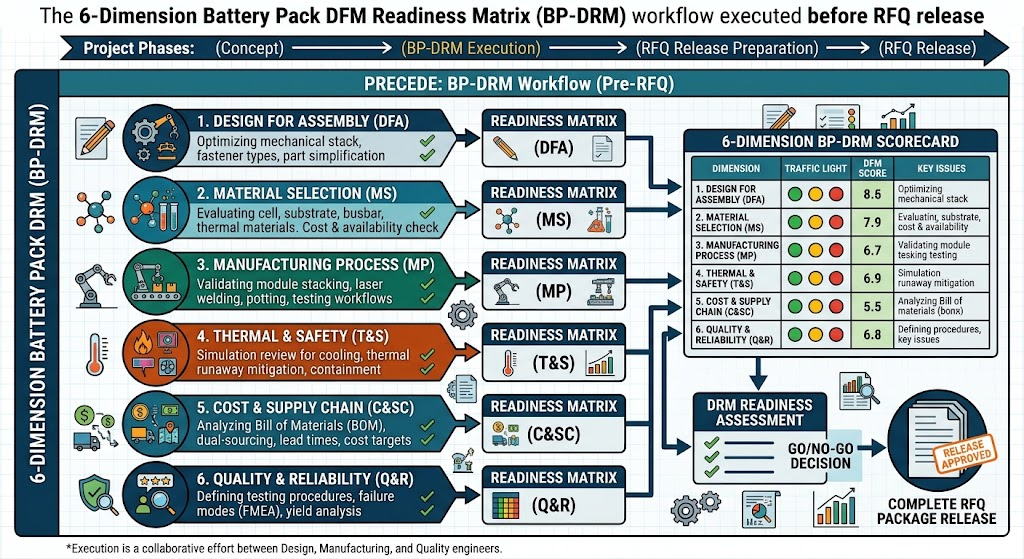
The 6-Dimension Battery Pack DFM Readiness Matrix (BP-DRM)
A complete battery pack DFM review evaluates more than physical envelope dimensions and nominal ampere-hour ratings. To guarantee reproducible manufacturing yield, structural safety, and long-term electrochemical balance, engineering teams should assess RFQ submissions using the 6-Dimension Battery Pack DFM Readiness Matrix (BP-DRM).
| Evaluation Dimension | Critical Quantitative Metric | Factory Floor Failure Mode (If Unchecked) | Standard Reference |
|---|---|---|---|
| 1. Electrochemical Binning | ΔV ≤ 3mV, ΔACIR ≤ 0.3mΩ, ΔC ≤ 1.0% | Premature pack capacity fade, aggressive thermal imbalance | IEC 61960-3 |
| 2. Interconnect Integrity | Pull force > 120N; Joint resistance < 0.05mΩ | Micro-crack tab detachment under vibration, localized I²R overheating | ISO 14555 / AWS D17.1 |
| 3. AFE Sensing Precision | ±1.5mV cell resolution; 4-wire Kelvin current sensing | False over/under-voltage trips, inaccurate Coulomb counting SOC drift | TI BQ / ADI LTC App Notes |
| 4. Passive Thermal Barrier | 1.0–2.0mm aerogel (λ ≤ 0.022 W/m·K); vent ΔP 20–50 kPa | Single-cell thermal runaway cascading into adjacent series groups | UL 9540A / UL 2580 |
| 5. Environmental & Dynamic DFM | 10–200Hz @ 8g vibration; 150g @ 6ms shock; IP67/IP68 | Housing stress fracturing, weld fatigue, water ingress short circuits | UN 38.3 T1–T8, IEC 60529 |
| 6. MES Traceability | 100% Data Matrix serialization (Cell OCV, IR, Weld Joules, EOL) | Uncontained broad product recalls from unsegregated production lots | ISO 13485 / ISO 9001 |
Implementing the BP-DRM framework ensures that engineering choices made during prototyping match mass production capabilities. For bespoke platforms, our engineers apply this matrix directly within our custom battery pack engineering workflows to validate mechanical, electrical, and thermal parameters prior to physical pilot builds.
Electrochemical & Cell Selection Feasibility
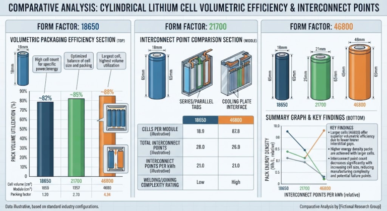
Form-factor selection defines the boundaries for pack volumetric packaging efficiency, automated production velocity, and thermal dissipation paths. Evaluating cylindrical (18650/21700), prismatic Lithium Iron Phosphate (LiFePO4), and pouch configurations requires balancing mechanical and electrochemical trade-offs before finalizing enclosure tooling.
| フォームファクター | Gravimetric Density (Wh/kg) | Interconnect & Tooling Complexity | Lifecycle Mechanical Swelling Behavior | DFM Verification Bottlenecks |
|---|---|---|---|---|
| Cylindrical (21700 / 18650) | 240 – 290 (NMC) 150 – 180 (LFP) |
High weld count; highly automated via wire bonding or optical fiber laser welding. | Zero external dimensional change; axial internal jelly-roll expansion managed by rigid steel casing. | High busbar weld density; thermal boundary isolation between tight cell matrices; current sharing balance across parallel arrays. |
| Prismatic Hard-Case | 160 – 210 (LFP) 220 – 250 (NMC) |
Low weld count; thick rigid copper/aluminum busbars requiring high-power wobbling laser welds. | Broad-face swelling: 3% to 5% expansion across operating lifecycle, requiring external mechanical pre-load containment. | End-plate structural sizing; compressive spring pack calculation; uniform insulation pad tolerance under sustained cycling. |
| Pouch (Laminated Film) | 260 – 310 (NMC) 140 – 170 (LFP) |
Delicate tabs; requires ultrasonic tab-to-busbar welding or micro-resistance clamping. | Progressive thickness expansion (up to 8-10%) plus potential gassing; demands continuous surface compression. | Edge seal stress relief; tab tear-off mitigation during shock/vibration; complex thermal conduction fin integration. |
When selecting prismatic chemistries for grid-scale or industrial applications, reviewing our engineering guidelines for industrial LiFePO4 battery pack design helps ensure mechanical compression fixtures correctly accommodate cyclic cell swelling.
For high-reliability series-parallel architectures, automated cell binning is mandatory to prevent premature capacity fade and unmanageable balance currents. At JHY Battery, incoming cell lots undergo strict automated screening:
- Open Circuit Voltage (OCV): Binned within ΔV ≤ 3mV across the lot.
- AC Internal Resistance (1kHz ACIR): Matched within ΔACIR ≤ 0.3mΩ.
- Discharge Capacity: Matched to ΔC ≤ 1.0% at a controlled 0.5C discharge rate.
- Static K-Value Screening: Cells are quarantined for 14 to 28 days to calculate self-discharge rates using the equation:
Where V1 is the initial resting voltage, V2 is the voltage measured after static aging, and t2 – t1 is the quarantine duration (minimum 14 days). Any cell showing a K-value 15% higher than the batch median is flagged and rejected for internal micro-dendrite formation risk.
Continuous vs. Peak Thermal Derating Boundaries
Battery specifications often state wide operating windows (e.g., -40°C to +60°C) without separating charging physics from discharging performance. Releasing an RFQ without explicit charge versus discharge thermal boundary definitions risks critical field failures.
Thermal Boundary Mandate: The standard ambient charging window is strictly 0°C to +45°C. Attempting to charge lithium-ion cells below 0°C without an active heating system forces lithium ions to plate onto the graphite anode surface as metallic lithium rather than intercalating. This creates metallic lithium dendrites that pierce the polyolefin separator, causing permanent capacity loss and unrecoverable internal short circuits.
Discharging, conversely, can safely take place at temperatures down to -40°C when using low-temperature electrolyte blends with low-viscosity carboxylate esters. At JHY Battery, our sub-zero cells retain ≥75% nominal capacity at -20°C (0.2C rate) and ≥55% capacity at -40°C. Designers must define operational current derating curves according to ambient boundary conditions:
Pack continuous current limits are governed by internal heat generation, calculated using the aggregate equivalent series resistance (ESR):
Where Ploss is the total heat generated in watts, IRMS is the continuous root-mean-square load current in amperes, and RESR_total is the total internal DC resistance across cells, interconnects, and busbars. Without forced convection or direct conductive heat sinking, continuous current must be derated to maintain cell core temperatures below 55°C (for NMC chemistries) or 60°C (for LiFePO4 chemistries).
Mechanical Architecture, Busbars, and Interconnect DFM
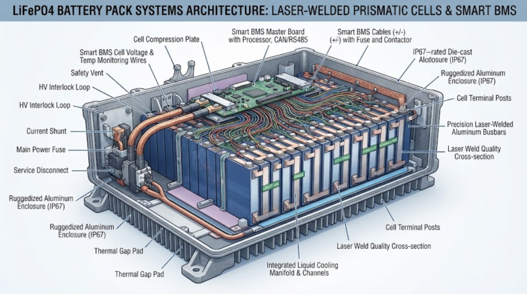
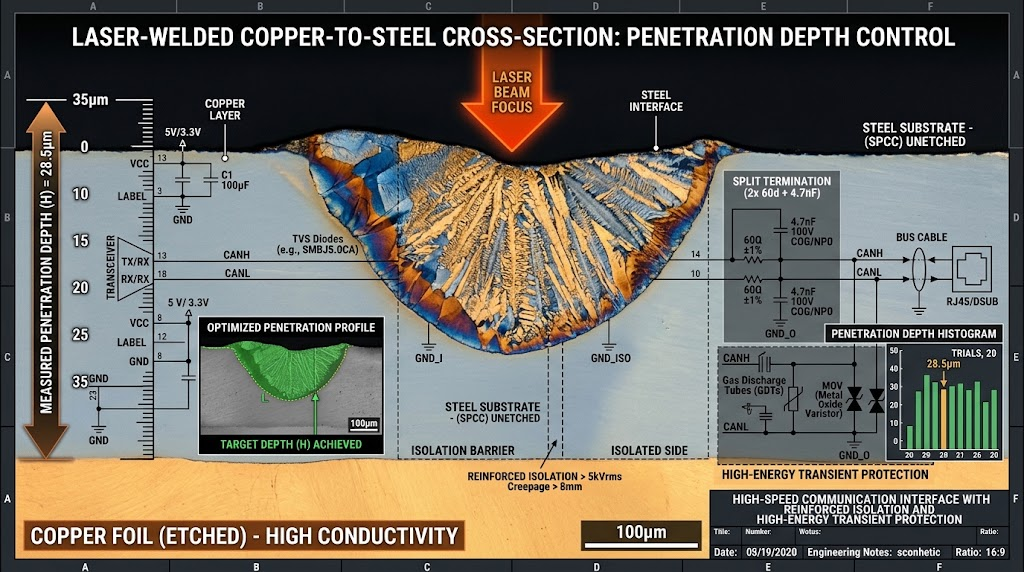
Interconnect failure remains a common defect vector during vibration and thermal cycling. Busbar design requires balancing cross-sectional ampacity, laser welding beam clearances, and thermal expansion relief.
For continuous high-current architectures (≥30A), pure copper (C1100-H02) or nickel-clad copper busbars should be used instead of pure nickel strip. The cross-sectional area of the conductor must maintain an electrical current density between 3.0 and 4.0 A/mm² under natural convection conditions:
Where Icont is continuous current in amperes, and Jtarget is the target current density (typically 3.0 to 4.0 A/mm²). For an 80A continuous system, busbar cross-sectional area should measure at least 20mm² (e.g., 10mm width × 2.0mm thickness).
Interconnect welding requires evaluating clear manufacturing trade-offs:
- Resistance Spot Welding: Best suited for thin pure nickel strip (≤0.2mm) onto cylindrical steel terminals at currents under 15A. Contact resistance runs relatively high (0.15 to 0.30 mΩ per joint).
- 1070nm Fiber Laser Welding: Required for thick copper (≥0.5mm) and copper-to-aluminum joints on prismatic terminals. Laser welding lowers contact resistance below 0.05 mΩ per joint and produces peel strengths exceeding 120N without subjecting delicate internal cell seals to excessive heat.
Laser welding heads require minimum vertical clearances of 45mm to 65mm, alongside optical beam entrance angles within ±12° of the normal axis. Tooling must also incorporate vacuum fume extraction ports to keep spatter off optical protective covers and bare cell gaskets.
Structural Damping, Anti-Fatigue Tab Relief, and Enclosure Integrity
Under transportation and field operations, battery packs face harmonic vibrations and high mechanical shocks. Passing the UN 38.3 standard (T3 vibration, 10Hz to 200Hz with 8g peak acceleration; T4 mechanical shock, 150g at 6ms half-sine) requires mechanical isolation between structural stresses and current-carrying tab joints.
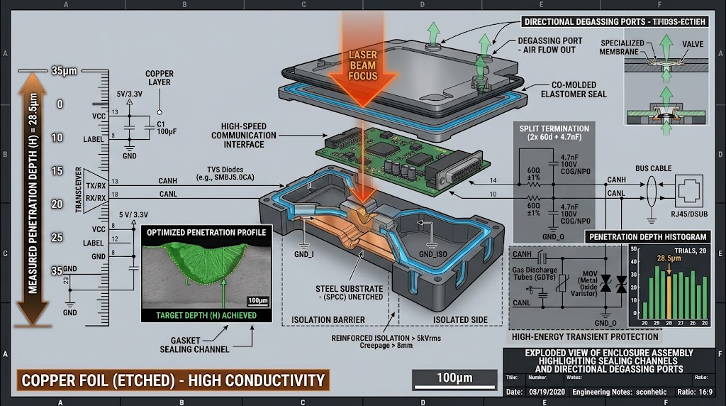
Rigid busbars fastened between cells without stress-relief bends act as mechanical levers during vibration, fracturing terminal posts or tearing weld seams. Busbars should feature an engineered stress-relief loop (omega bend) with a bend radius at least 1.5x the material thickness.
Enclosure designs must also incorporate the following mechanical features:
- Material Selection: Die-cast aluminum (ADC12/A380) for rigid thermal conduction, or flame-retardant polycarbonate/ABS blends rated UL 94-V0 with wall thicknesses ≥ 2.5mm.
- Ingress Protection (IP67/IP68): Molded continuous silicone or EPDM gasket channels with a continuous 25% to 30% compression ratio, fastened by perimeter bolts spaced no more than 40mm apart.
- Directional Pressure Relief Venting: A dual-stage, ePTFE hydrophobic membrane vent combined with an integrated burst disc calibrated between 20 kPa and 50 kPa (ΔP). This permits routine pressure equalization during temperature swings while providing directional exhaust venting during off-gassing to prevent violent enclosure rupture.
Smart BMS Electronics & Wire Harness Integration DFM
BMS failures often originate from PCB layout routing issues and electrical noise rather than core semiconductor faults. Designing stable BMS hardware begins with selecting industrial or automotive Analog Front-End (AFE) ICs (such as the Texas Instruments BQ76952 or Analog Devices LTC6811/LTC6813), which deliver ±1.5mV voltage sensing accuracy across operating temperatures.
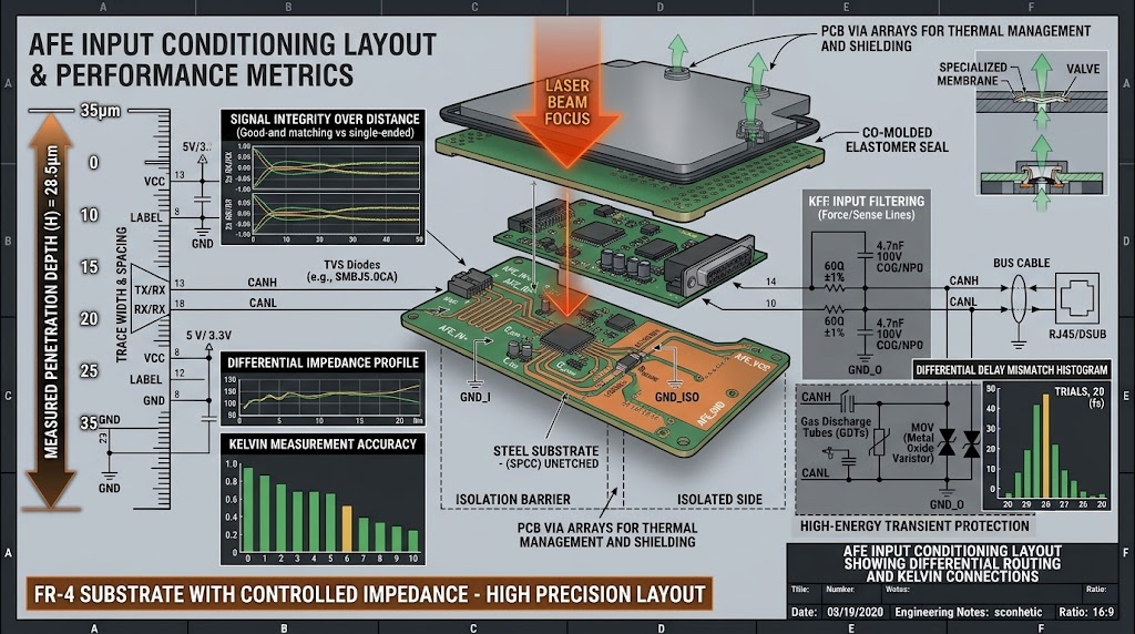
Critical BMS physical layout guidelines include:
- Current Shunt Routing: Use a true 4-wire Kelvin connection. Sensing traces must route from the inner contact pads of the surface-mount shunt resistor as a tightly coupled differential pair directly to the AFE current sense pins, isolated from ground planes carrying high transient currents.
- Cell Voltage Sense Conditioning: Every cell input track requires symmetrical RC low-pass differential filtering (100Ω resistor + 100nF filter capacitor) placed within 10mm of the AFE pins. This protects the inputs from high-frequency pulse-width modulation (PWM) noise and inverter switching transients.
- High-Voltage Creepage and Clearance: For modular packs operating above 60V DC, meet IEC 60664-1 standards with creepage distances ≥ 3.2mm and clearance gaps ≥ 2.5mm over Pollution Degree 2 surfaces.
For complex multiphase industrial systems, our engineering team assists with layout verification and communications setup through our dedicated smart BMS architecture and layout services.
LFP Voltage Plateau Fuel-Gauging & Quiescent Sleep Budgets
LiFePO4 chemistry presents a well-known fuel-gauging challenge: an exceptionally flat open-circuit voltage (OCV) profile across the 20% to 80% state-of-charge (SOC) window. Within this region, a 1mV voltage drop can equate to a 5% to 8% change in available capacity.
Voltage-based threshold gauging cannot accurately calculate remaining energy in LiFePO4 cells. Firmware architectures must pair high-resolution Coulomb counting (via a 16-bit to 24-bit delta-sigma ADC) with an Extended Kalman Filter (EKF) algorithm. The EKF dynamically updates its internal cell resistance model across temperature to maintain SOC accuracy within ±2.0%.
Prolonged storage presents another common field-failure mode: excessive BMS quiescent current. If quiescent current exceeds 50μA in warehouse storage, pack self-discharge drops cell voltages below 1.5V. At this low potential, copper current collectors dissolve into the electrolyte; re-charging then forms copper dendrites that cause catastrophic internal short circuits.
DFM Quiescent Sleep Standard: Total BMS sleep-mode current consumption across all AFE pins, microcontrollers, and active safety switches must not exceed 10μA. Packs with integrated smart displays or telematics modules must feature an automatic deep-sleep cut-off switch after 72 hours of idle bus activity.
Thermal Management & Passive Safety Engineering
To pass UL 9540A and IEC 62619 safety standards, modern lithium-ion packs must prevent a single cell in thermal runaway from cascading into neighboring cells. When a cell vents violently, it releases hot gases and ejecta exceeding 600°C within fractions of a second.
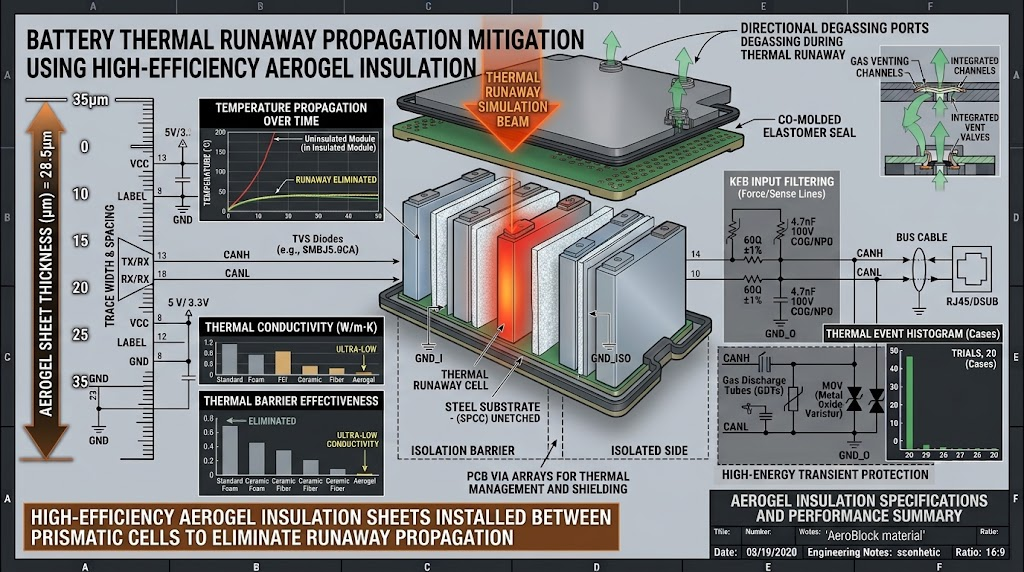
Pack mechanical designs should incorporate passive propagation barriers between adjacent parallel or series cell faces:
- Silica Aerogel Insulation Blankets: 1.0mm to 2.0mm thickness with thermal conductivity λ ≤ 0.022 W/(m·K). Aerogel holds adjacent cell skin temperatures below 120°C even when the triggering cell surpasses 650°C.
- Phlogopite Synthetic Mica Sheets: Withstand continuous flame impingement up to 1000°C, providing electrical insulation and fire resistance around high-voltage busbars and module covers.
- Strategic NTC Thermistor Placement: Surface temperatures vary across a module. NTC temperature sensors must mount directly on current-carrying positive busbar interfaces and in the geometric center of the cell array (the natural heat accumulation core), not on exposed outer enclosure walls.
For applications where unexpected shutdowns present life-critical hazards, our team integrates redundant multi-point temperature sensors through our ISO 13485 medical device battery integration engineering group.
Extreme Environment Adaptation: Sub-Zero Charging & High-Temp Operation
Deployments in arctic environments, cold-chain monitoring, or telematics require specialized sub-zero battery engineering. At temperatures below -20°C, standard alkyl carbonate electrolytes freeze, which severely increases cell internal resistance and drops terminal voltage under load.
For cold-climate systems, packs should feature integrated 12V or 24V flexible silicone heating mats or ceramic Positive Temperature Coefficient (PTC) heaters. These heating circuits are managed directly by smart BMS firmware:
- When charge current is detected at ambient temperatures below 0°C, the BMS isolates the battery charge path using solid-state MOSFETs or electromechanical contactors.
- Incoming power directs entirely to the integrated heating mats to warm the pack core.
- When internal NTC sensors verify the core cell structure has reached +5°C (±2°C hysteresis), the BMS closes the main charge path and permits battery charging.
For details on low-temperature chemistry selection and heating circuit specifications, explore our validated solutions for extreme low-temperature battery chemistries.
Battery Pack DFM Engineering Watch-Outs & Boundary Checklist
This verification checklist highlights primary engineering thresholds and empirical boundaries. Cross-reference these parameters before releasing an OEM/ODM production RFQ.
| Design Domain | Critical Checkpoint Parameter | Quantitative Boundary / Pass-Fail Target | Engineering Risk / Failure Impact |
|---|---|---|---|
| Cell Matching | Static Voltage & Resistance Sorting | ΔV ≤ 3mV, ΔACIR ≤ 0.3mΩ (1kHz), ΔC ≤ 1.0% | Capacity imbalance, premature BMS cutoff, thermal variance. |
| Cell Matching | Self-Discharge Screening (K-value) | 14–28 days aging; reject outliers > 15% above median | Internal micro-short circuit failures during service life. |
| Interconnect | Laser Weld Clearance & Angle | Vertical clearance ≥ 50mm; tilt angle ≤ ±12° | Beam clipping, cold welds, excessive heat-affected zones (HAZ). |
| Interconnect | Mechanical Weld Joint Pull Strength | Peel/Shear force > 120N per weld group | Tab detachment under UN 38.3 vibration or mechanical shock. |
| BMS Hardware | Current Shunt Kelvin Traces | Dedicated differential pair, isolated from GND planes | Current measurement offsets, inaccurate Coulomb counting. |
| BMS Hardware | Deep Sleep Quiescent Drain | I_sleep ≤ 10μA total system drain | Permanent cell bricking and copper dendrites during shipping. |
| Thermal Design | Single-Cell Thermal Barrier | Aerogel sheet (≥1.0mm, λ ≤ 0.022 W/m·K) | Cascading thermal runaway across adjacent series/parallel cells. |
| Safety Venting | Dual-Stage Directional Exhaust | Burst pressure calibrated to ΔP = 20 to 50 kPa | Violent enclosure explosion under cell off-gassing events. |
| コンプライアンス | Creepage and Clearance | Creepage ≥ 3.2mm, clearance ≥ 2.5mm (>60V DC) | Dielectric breakdown, tracking arcs, and regulatory test failures. |
OEM RFQ Package & Industrial Manufacturing Hand-Off
Releasing a complete, production-ready RFQ package helps avoid weeks of engineering back-and-forth and quote adjustments. A thorough RFQ submission package should contain the following items:
- 2D Engineering Drawings with GD&T: Explicitly define datum references on primary cell locating fixtures, PCB mounting bosses, and critical overall envelope dimensions with clear geometric tolerances.
- 3D Native/STEP CAD Models: Complete assemblies showing cell spacings, busbar structures, wire harness channels, thermal barrier locations, and exterior connector interfaces.
- Electrical System Schematics: Full wiring schematics covering series/parallel arrangements, AFE sensing harness pinouts, thermistor locations, fuse coordination curves, and communications interfaces (CAN, SMBus, RS485).
- Duty Cycle & Operational Profiles: Nominal and peak discharge currents, pulse durations, end-of-discharge cut-off voltages (EODV), target cycle life, and ambient charge/discharge temperature extremes.
Every custom pack produced by JHY Battery passes through automated end-of-line (EOL) test stations. These systems record full charge/discharge cycling curves, verify ACIR, test communication buses, and measure safety insulation resistance before serializing individual pack QR codes into our factory MES database.
Frequently Asked Questions (Engineering & DFM Verification)
How do you verify genuine Grade-A cell binning and detect counterfeit or downgraded stock?
Authentic Grade-A status is confirmed by auditing original factory 2D Data Matrix barcodes directly against primary manufacturer production logs for capacity, OCV, and ACIR. At factory incoming inspection, cells undergo a 14 to 28-day static quarantine to calculate their daily self-discharge rate (K-value). Any cell with an ACIR variance exceeding 0.3mΩ at 1kHz, a K-value deviating more than 15% from the batch median, or visual terminal polishing marks is flagged as B-grade or repurposed inventory and rejected.
When should an engineer specify fiber laser welding over resistance spot welding for busbars?
Resistance spot welding is acceptable for low-current applications (under 15A continuous) using thin nickel tabs (≤0.2mm) on cylindrical steel cans. For high-current packs (≥30A continuous) requiring pure copper (0.8mm to 1.5mm) or copper-aluminum bimetallic busbars, continuous-wave or wobbling fiber laser welding (1070nm) is necessary. Laser welding produces joint contact resistances below 0.05mΩ, limits heat input to the cell’s internal seals, and provides pull/shear strengths exceeding 120N.
How do you prevent fatigue cracking on weld tabs during UN 38.3 vibration testing?
Tab cracking during UN 38.3 T3 vibration testing (10Hz to 200Hz, 8g peak) occurs when relative motion develops between the cell matrix and the rigid BMS or housing. Mechanical designs should incorporate cell cradles molded from rigid polycarbonate/PBT that clamp the cells securely, paired with omega-shaped expansion loops on all busbar interconnects. This prevents dynamic pack stresses from transferring directly to the laser or ultrasonic weld joints.
How does smart BMS architecture correct for LiFePO4 flat-voltage curve SOC drift?
Because the open-circuit voltage profile of LiFePO4 remains nearly flat across 20% to 80% SOC, standard voltage-table lookups can drift significantly over time. Smart BMS designs resolve this by pairing high-resolution Coulomb counting (via a 16-bit to 24-bit delta-sigma ADC and precision current shunt) with an Extended Kalman Filter (EKF) algorithm. The algorithm recalibrates SOC reference points whenever the pack reaches upper charge cut-off or lower knee discharge thresholds.
Execute Your Pack DFM with JHY Battery: 3-Step Action Plan
For more than 30 years, JHY Battery (China Battery Manufacturer) has delivered precision industrial lithium battery manufacturing. With an audited 0.03% (300 PPM) defect rate, an engineering team of over 800 hardware and electrochemical specialists, and ISO 13485, ISO 9001, UL 1642, UL 2054, CE, and UN 38.3 accreditations, we help teams transition battery designs smoothly from initial CAD modeling to volume production.
Move from Engineering DFM to Functional Prototyping
Use our structured 3-step intake workflow to review your pack architecture before locking in hard production tooling:
- Electrochemical Architecture & Load Profiling: Provide your operating C-rates, envelope dimensions, nominal voltage, target life cycle, and expected ambient extremes for an initial design review.
- DFM Analysis, Structural Simulation & Thermal Layout: Our engineering team completes a detailed DFM assessment, weld clearance check, busbar sizing review, and thermal model within 48 hours.
- Rapid Prototyping & Compliance Validation: Receive fully functional, tested prototypes in 5 to 7 business days, accompanied by complete cell binning data, weld pull-test logs, and quality documentation.
Direct Engineering Support:
Email: Simple@chinabatterymanufacturer.com | joeshen@chinabatterymanufacturer.com
Direct Technical Line / WhatsApp: +86-18575997879