How to Optimize Battery Life for GPS Asset Trackers
Core Engineering Principles for GPS Asset Tracker Power Optimization
Optimizing battery life for unpowered GPS asset trackers requires balancing radio frequency transmissions, satellite acquisition intervals, power management integrated circuits (PMICs), and battery chemistry dynamics. Minimizing high-drain cellular states and leveraging deep sleep modes allows battery lifespans to extend from weeks to several years in remote industrial environments.
- Optimize Reporting Intervals: Shift from continuous pinging to motion-triggered or schedule-based interval transmissions.
- Enable Cellular Sleep Modes: Configure 3GPP Power Saving Mode (PSM) and eDRX to minimize network re-attachment current.
- Implement Inertial Wake-Up: Use ultra-low-power accelerometers to trigger GPS fixes only during physical asset movement.
- Select Matched Chemistries: Deploy temperature-resilient Lithium Thionyl Chloride (LiSOCl2) or rechargeable LiFePO4 cells to match target operational profiles.
- Streamline Firmware Routines: Truncate GNSS search timeouts, optimize delta FOTA packages, and offload indoor fixes to Wi-Fi/BLE location engines.
The Power Consumption Hierarchy: Modem RF vs GNSS vs Sensor Standby
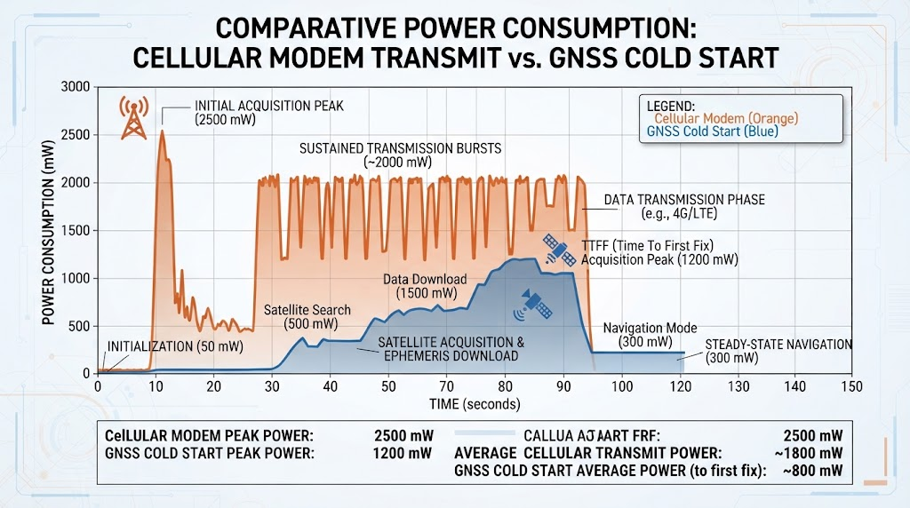
Understanding where energy is consumed within an Internet of Things (IoT) telematics device is critical for writing efficient power budgets. Many engineers assume the Global Positioning System (GPS) receiver represents the largest energy drain, but radio frequency (RF) transmissions and network registration routines draw significantly more current.
Energy Distribution Baseline: Cellular modem network acquisition and data transmission consume the largest share of milliwatt-hours in asset tracking devices, followed by GNSS receiver satellite lock routines, while onboard microcontrollers and MEMS sensors draw minimal energy during sleep cycles.
Cellular modems operating on LTE Cat-M1 or NB-IoT can draw peak transmit currents exceeding 250 mA to 400 mA depending on network coverage conditions. Cellular network re-registration and search in fringe signal zones consumes up to 80% more energy than a single cold-start GNSS fix. When an asset is placed inside a metal shipping container or dense warehouse, the modem repeatedly boosts power output to connect to base stations, rapidly draining battery reserves.
| Hardware Subsystem | Active Current Draw | Sleep/Idle Current | Avg. On-Time per Event | Power Impact |
|---|---|---|---|---|
| Cellular Modem (LTE-M TX) | 180 mA – 400 mA | 3 µA – 15 µA (PSM) | 3 – 12 seconds | Critical (High) |
| GNSS Receiver (Cold Fix) | 15 mA – 45 mA | 1 µA – 5 µA | 25 – 45 seconds | High |
| GNSS Receiver (Hot Fix) | 15 mA – 45 mA | 1 µA – 5 µA | 1 – 3 seconds | Low |
| Wi-Fi Sniffing Radio | 60 mA – 120 mA | 0.5 µA | 0.5 – 1.5 seconds | Very Low |
| MCU + 3-Axis MEMS Sensor | 2 mA – 8 mA | 1.5 µA – 4 µA | Always Sensing | Negligible |
A standard cold-start GNSS fix requires downloading ephemeris data from visible satellites, keeping the receiver active for 30 seconds or more. If the receiver loses signal under structural shielding, power management software must prevent endless satellite search loops by imposing strict Time-to-First-Fix (TTFF) timeout limits according to published 3GPP Technical Specifications.
Battery Chemistry and Hardware Selection for Extended Deployments
Hardware power architecture begins with cell chemistry selection. Choosing the right power source depends on whether the tracking deployment demands high single-use capacity or cyclic recharging capability.
Primary Lithium Chemistries: LiSOCl2 vs Li-MnO2
For non-rechargeable unpowered asset tracking lasting 3 to 10 years, Lithium Thionyl Chloride (LiSOCl2) is the industry standard. LiSOCl2 offers an energy density of up to 650 Wh/kg and a self-discharge rate under 1% per year at 20°C.
However, LiSOCl2 cells develop an internal passivation layer (lithium chloride film) on the lithium anode during storage. While this layer prevents self-discharge, it causes an initial voltage drop when high-pulse cellular currents are pulled.
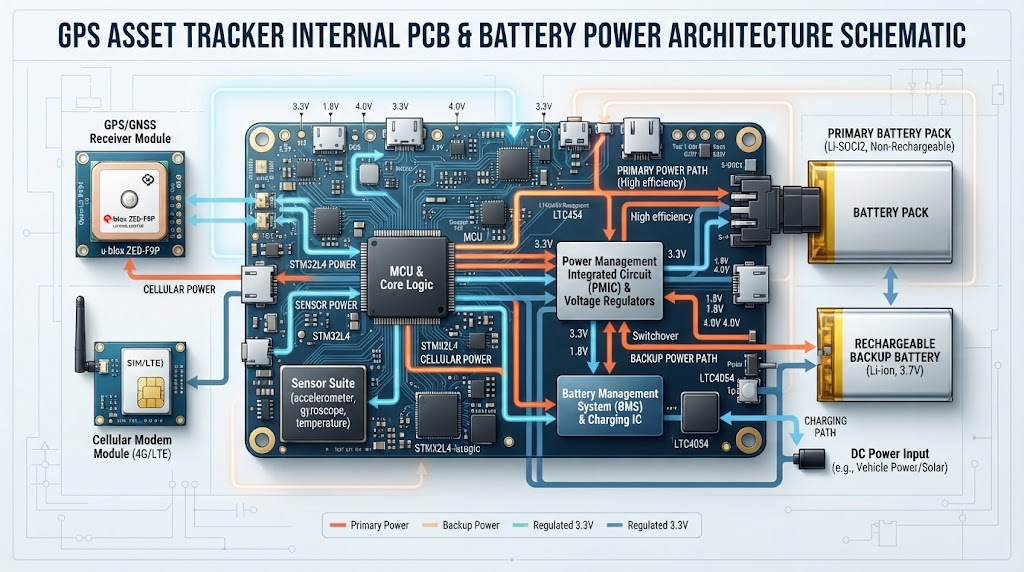
Engineering Rule on Passivation: Pair bobbin-type LiSOCl2 cells with Hybrid Layer Capacitors (HLC) or supercapacitors to supply the 250 mA–500 mA peak pulses required during LTE-M/NB-IoT transmissions without dropping below the modem’s minimum operating voltage cutoff.
Operating LiSOCl2 primary lithium cells at continuous temperatures below -20°C results in a temporary 20% to 35% reduction in usable milliamp-hour (mAh) capacity without proper passivation management. In comparison, Lithium Manganese Dioxide (Li-MnO2, 3.0V) provides higher immediate pulse capability without severe passivation, though with lower overall volumetric energy density.
Rechargeable Chemistries: LiFePO4 vs Traditional Lithium-Ion
When tracking devices leverage solar harvesting or vehicle power harvesting, Lithium Iron Phosphate (LiFePO4) is often preferred over standard Lithium Nickel Manganese Cobalt (NMC). LiFePO4 cells support 2,000 to 5,000 charge cycles and operate safely across wide industrial temperature ranges (-20°C to +60°C) without the thermal runaway risks seen in consumer-grade pouch cells.
Cellular Network Protocol Optimization: Configuring PSM and eDRX
Legacy 2G and 3G cellular trackers maintained persistent network connectivity, keeping RF baseband processors in high-current idle states (10 mA to 25 mA). Modern LPWAN (Low-Power Wide-Area Network) technologies such as LTE-M (eMTC) and Narrowband IoT (NB-IoT) introduce power architectures optimized for dormant field hardware.
Configuring 3GPP Power Saving Mode (PSM)
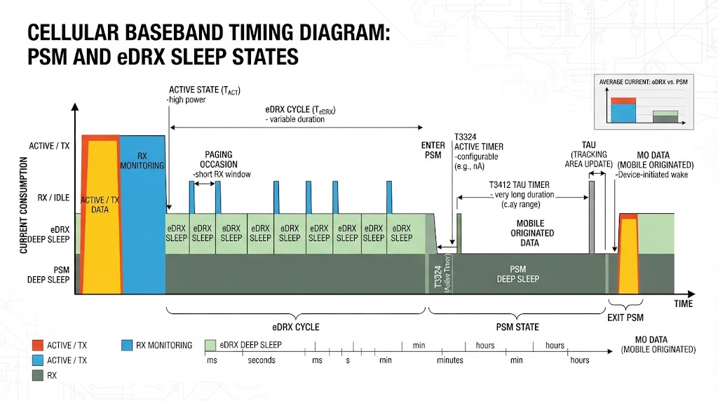
PSM allows an IoT tracker to enter a deep dormant state while remaining registered with the cellular network. The device avoids having to re-run network attachment handshakes when waking up to send data.
- Active Timer (T3324): Sets how long the radio stays reachable for downlink messages after completing a data uplink (e.g., 2 to 16 seconds).
- Extended Periodic TAU (T3412): Defines the periodic Tracking Area Update window (e.g., once every 12 to 72 hours), maintaining network registration without full cellular attachment re-negotiation.
Enabling 3GPP Power Saving Mode (PSM) can reduce idle tracker current consumption from 15 mA down to under 3 to 5 microamps (µA). This allows tracking hardware to run on compact battery packs for multi-year lifespans.
Extended Discontinuous Reception (eDRX)
If an asset tracking device must remain reachable for real-time remote commands (such as activating a buzzer or changing ping rates), eDRX extends paging cycles. Rather than listening to the network every 1.28 or 2.56 seconds, the modem checks in at configured intervals (e.g., every 20.48 to 40.96 seconds), cutting paging current draw by more than 80% compared to non-eDRX configurations.
Hybrid Positioning Architecture: Offloading GNSS to Wi-Fi and BLE
Standard GNSS positioning uses significant battery power because the baseband processor must stay powered for extended periods to lock onto multiple orbital satellite signals. Implementing a hybrid geolocation fallback strategy avoids running complete GNSS acquisition cycles when high precision is unnecessary.
Wi-Fi MAC Sniffing and Cell Tower Triangulation
Instead of powering on a GNSS receiver inside a distribution center or freight depot, the tracker can wake an ultra-low-power Wi-Fi receiver for 500 milliseconds. The device captures the BSSIDs and signal strengths (RSSI) of surrounding Wi-Fi routers without authenticating to them.
- Energy Consumption: Wi-Fi sniffing draws roughly 0.01 mAh per fix compared to 0.35–0.80 mAh for a cold-start GNSS fix.
- Indoor Reliability: Accurately resolves location down to 10–30 meters indoors, where satellite signals are obstructed.
- Cell-ID Trilateration: In remote regions, fallback to cellular baseband Cell-ID location yields 200m to 2km accuracy with zero additional battery cost beyond the telemetry packet payload.
Cloud-Assisted GNSS (A-GNSS / Ephemeris Injection)
When high-precision GPS coordinates are required, injecting orbital ephemeris and almanac data into the receiver over the cellular link eliminates the need for the device to download data directly from satellites at 50 bps. This reduces TTFF from 40 seconds down to 2 to 4 seconds, cutting GNSS engine energy consumption per fix by up to 85%.
The 4-Tier TRAC Power Optimization Protocol
In telematics engineering, setting fixed 15-minute ping rates without considering operational context leads to battery depletion. Our engineering team uses the TRAC Power Optimization Protocol (Transmission, Receiver, Acceleration, Chemistry) to align firmware behavior with physical asset dynamics.
1. Transmission Governance (Radio RF)
Batch location fixes into single data packets. Rather than powering the cellular modem to transmit every single fix, log 12 to 24 location points into non-volatile SPI flash memory and transmit them in one cellular burst. This eliminates repetitive network attachment overhead.
2. Receiver Truncation (GNSS Engine)
Hard-code satellite search limits. If a GNSS fix cannot be obtained within 45 seconds due to shielding (such as within an underground depot or stacked container yard), abort the satellite search immediately, tag the log with the last known Cell-ID, and enter deep sleep.
3. Acceleration Filtering (Motion Dynamics)
Keep the main microcontroller and radios in deep sleep while the asset remains stationary. Configure an interrupt pin on a 3-axis ultra-low-power accelerometer (drawing < 2 µA). Wake the system only when continuous movement exceeds an established acceleration and time threshold (e.g., > 0.15G for > 5 seconds).
4. Chemistry & Passivation Routine
Implement scheduled background micro-pulses in firmware if using LiSOCl2 primary batteries. In long dormant states, trigger periodic current pulses through a load resistor or the modem baseband to prevent passivation layers from creating excessive voltage lag during sudden wakeups.

Use-Case Specific Configuration Profiles and Benchmarks
Different asset deployment environments require distinct balancing of battery capacity against update frequency. The table below outlines real-world benchmarks achieved through matched power configurations.
| Deployment Scenario | Battery Chemistry & Capacity | Tracking & Ping Profile | Power State Strategy | Estimated Lifespan |
|---|---|---|---|---|
| Intermodal Shipping Container | LiSOCl2 (19,000 mAh D-Cell + HLC) | 1 fix every 12 hrs (Stationary) 1 fix every 2 hrs (In Motion) |
LTE-M with deep PSM (3 µA standby), Cloud-Assisted GNSS | 6.5 – 8.0 Years |
| Cold-Chain Refrigerated Trailer | LiFePO4 (6,400 mAh Rechargeable) | Temp logging every 5 mins Cellular upload every 1 hr |
eDRX mode with external trailer power charging input | 3 – 5 Years (Cyclic) |
| Remote Heavy Construction Equipment | Li-MnO2 (10,500 mAh Industrial Pack) | Vibration-triggered wake-up Operating hours logging |
Stationary deep sleep (< 5 µA), Wi-Fi sniffing fallback | 4.0 – 5.5 Years |
| High-Value Air Cargo Pallet | LiFePO4 / Li-Metal (3,200 mAh Thin-Pack) | Periodic beaconing + Flight Mode detection via barometric sensor | RF completely disabled in flight, Wi-Fi + BLE trilateration at hub | 12 – 18 Months |
Firmware Over-the-Air (FOTA) Maintenance Without Depleting Reserves
Firmware Over-the-Air (FOTA) updates are essential for maintaining security patches and optimizing telematics codebases. However, an unmanaged FOTA cycle can rapidly deplete battery capacity or brick a field-deployed tracker.
Downloading a full 2 MB to 5 MB binary file over a constrained cellular connection requires continuous high-current modem receiver states lasting several minutes. This single operation can consume the equivalent of several months of normal operational battery power budget.
“Uncontrolled FOTA operations are one of the most common causes of unexpected field battery failure. If a modem attempts a large binary download in weak signal conditions, the combination of retransmissions and SPI flash write cycles can trigger a voltage drop below the hardware brownout reset threshold.”
— Dr. Robert Vance, Senior IoT Hardware Architecture Consultant
To safely execute remote firmware maintenance:
- Deploy Delta Updates: Send only the binary differential (delta) patches (often < 50 KB) rather than re-flashing the full system image.
- Impose Battery Voltage Thresholds: Enforce firmware checks preventing FOTA execution if open-circuit battery voltage is below 3.3V or if ambient cell temperature is under 0°C.
- Dual-Bank Flash Verification: Use dual-bank external SPI flash memory to verify image checksum integrity before initiating baseband flashing routines.
Frequently Asked Questions About GPS Asset Tracker Battery Life
How long do asset tracker batteries last in real-world conditions?
Depending on configuration, battery life spans from 6 months up to 10 years. An unpowered asset tracker utilizing an industrial primary LiSOCl2 battery pack configured with 3GPP PSM and reporting once per day will comfortably exceed 7 years of field operation. Increasing updates to once every 10 minutes drops operational life to roughly 6 to 12 months without solar assistance.
What is the battery life difference between LoRaWAN and LTE-M?
LoRaWAN consumes significantly less energy per uplink packet (transmitting on sub-GHz ISM bands with peak currents of 25 mA–40 mA) compared to LTE-M (which requires 180 mA–400 mA for cellular handshakes). However, LoRaWAN requires local gateway infrastructure. For cross-border logistics lacking dedicated gateway coverage, cellular LPWAN (LTE-M/NB-IoT) with PSM configured is the industry standard.
How does freezing weather impact GPS asset tracker batteries?
Sub-zero operating temperatures increase the internal resistance of all lithium battery chemistries. This causes a temporary operational voltage drop during high-current cellular transmissions. Using bobbin-type LiSOCl2 cells paired with Hybrid Layer Capacitors (HLC) prevents brownout resets down to -40°C, preserving operational reliability in cold-chain and arctic shipping.
How can I detect and mitigate battery passivation?
Battery passivation in primary lithium cells appears in telemetry logs as an abrupt voltage dip during the initial millisecond of a cellular transmission burst. Firmware should monitor load voltage versus resting voltage. If passivation is detected, the microcontroller can execute periodic low-current discharge pulses to safely depassivate the cell anode.
About the Author and Telematics Hardware Review Board
This technical guide was developed by custom battery engineers and telematics hardware specialists. Power profiling data was compiled using empirical testing methods, including Otii Arc high-precision power analyzers, multi-channel oscilloscopes, and environmental thermal chambers simulating industrial operating conditions from -40°C to +85°C according to IEEE Telematics Power Standards.
Need Custom Battery Packs for Your GPS Asset Trackers?
Get high-performance, custom-engineered primary and rechargeable lithium battery solutions matched directly to your IoT hardware power profile.